
The operational deployment of hydraulic gear pumps across industrial applications is both ubiquitous and continuous; however, empirical data indicate that fewer than 5% of manufacturers consistently attain the dimensional precision and geometric tolerances requisite for sustained leak-free operation under high-pressure service conditions. A rigorous examination of the manufacturing process elucidates the critical role that process control and quality assurance play in differentiating high-reliability hydraulic systems from those predisposed to premature degradation and systemic failure.
Making a hydraulic gear pump is one of those processes where every step matters more than you'd think. It starts with cutting precise tooth profiles into raw metal blanks and ends with pressure testing the finished unit to make sure nothing leaks under load. Here's a look at how the whole thing comes together, from rough castings and forgings all the way to a working fluid power component ready to ship.
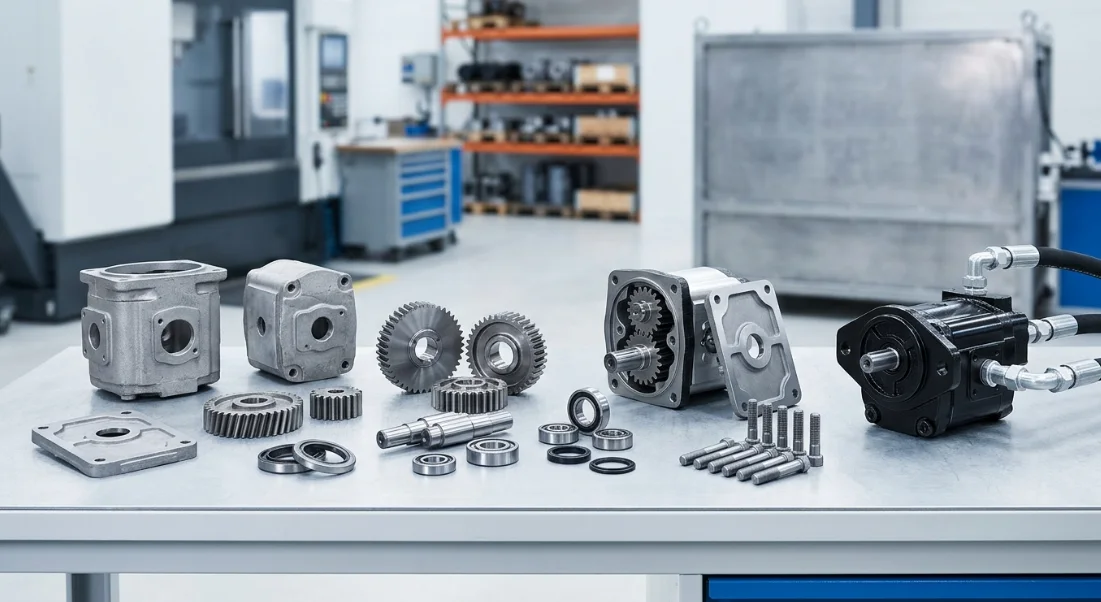
Overview of Hydraulic Gear Pump Manufacturing
The end-to-end hydraulic gear pump manufacturing workflow spans six major phases: raw material selection, gear machining, housing casting and finishing, secondary component production, assembly, and validation testing. Each phase feeds directly into the next, and a defect introduced at any stage compounds downstream.
Precision engineering is not optional — it is the baseline. Gear tooth profiles must hold ±0.005mm, housing bores must maintain concentricity within 0.01mm, and sealing surfaces must be flat to within a single light band. These numbers define whether a pump delivers rated flow or leaks under pressure.
Key Components of a Hydraulic Gear Pump
A standard external gear pump contains six core component groups, each with distinct material requirements and functional roles. Understanding these parts clarifies why hydraulic pump components machining demands such tight control.
| Component | Material | Primary Function |
|---|---|---|
| Drive Gear | Alloy Steel (20CrMnTi / 40Cr) | Converts mechanical energy to fluid flow |
| Driven Gear | Alloy Steel (20CrMnTi / 40Cr) | Meshes with drive gear to create displacement |
| Pump Housing | Cast Iron (HT250) / Aluminum (ADC12) | Contains fluid and maintains pressure |
| Front/Rear Plates | Hardened Steel | Seals gear chambers, minimizes internal leakage |
| Shaft Seals | Nitrile / Viton | Prevents external leakage |
| Bearings | Needle / Journal Type | Supports gear shafts under load |
The drive and driven gears form the heart of the pump. As they rotate, fluid is trapped between the gear teeth and the housing wall, then carried from the suction port to the discharge port. Volumetric efficiency depends directly on the clearances between these components.
Industry Standards and Tolerance Requirements
Hydraulic gear pump production is governed by ISO 4409 (hydraulic fluid power — positive displacement pumps and motors — determination of steady-state performance) and DIN standards for gear accuracy classification. These frameworks establish the measurement methods and acceptance criteria that separate industrial-grade pumps from unreliable ones.
Typical tolerance bands for a quality gear pump include gear tooth profile accuracy of ±0.005mm, housing bore concentricity ≤0.01mm, and end-plate flatness within 0.0003mm (1 light band). Meeting these numbers consistently across production batches requires process control at every machining station.
Raw Material Selection and Incoming Inspection
Material selection begins with application requirements. Gears destined for high-pressure pumps (250+ bar) typically use 20CrMnTi carburizing steel, which achieves HRC 58-62 surface hardness while retaining a tough core. Medium-duty applications may use 40Cr quenched and tempered steel for a balance of strength and machinability.
Housings follow a similar logic. HT250 cast iron handles high-pressure, heavy-duty service where rigidity and vibration damping matter. ADC12 aluminum die castings serve mobile and weight-sensitive applications at moderate pressures. Every incoming material lot must pass inspection before entering the production line.
Material Testing Protocols
Incoming inspection applies three primary quality gates. Spectrometric analysis confirms alloy composition matches the material certificate — a single percentage-point deviation in chromium or manganese content can alter heat treatment response and final hardness.
Hardness testing (Brinell for castings, Rockwell for bar stock) verifies that raw material falls within the specified range before machining begins. Ultrasonic flaw detection scans for internal voids, inclusions, or cracks that would cause catastrophic failure under cyclic pressure loading.
These protocols prevent downstream failures. A gear blank with a subsurface inclusion might pass hobbing and heat treatment only to crack at 2,000 hours of service — a failure mode that incoming inspection eliminates at minimal cost.
Precision Gear Hobbing Process
The precision gear hobbing process transforms heat-treated blanks into involute-profile gears with surface roughness Ra ≤ 0.4μm. This multi-step sequence — hobbing, shaving or shaping, heat treatment, and final grinding — determines the pump's flow characteristics, noise signature, and service life.
Each operation builds on the previous one. Hobbing establishes the basic tooth form, heat treatment hardens the surface, and grinding corrects any distortion while achieving final dimensional accuracy. Skipping or rushing any step produces gears that generate excessive noise, accelerated wear, or premature failure.
CNC Gear Hobbing and Shaping
Modern CNC hobbing machines produce gear teeth using a helical cutting tool (hob) that rotates in synchronization with the workpiece. Machine setup includes selecting the correct hob module, setting the helix angle, and programming feed rates that balance material removal with surface finish.
Cutter selection depends on the gear module and required accuracy class. Carbide-coated hobs running at 80–120 m/min cutting speed with 1.5–3.0 mm/rev axial feed produce DIN Class 7–8 accuracy in a single pass. Achieving DIN Class 6 typically requires a subsequent shaving or shaping operation to refine the tooth profile before heat treatment.
CNC control enables real-time compensation for thermal drift and tool wear, maintaining consistency across production runs of hundreds or thousands of gears. This repeatability is what separates modern gear pump assembly techniques from legacy manual methods.
Heat Treatment and Surface Hardening
After initial machining, gears undergo carburizing at 920–940°C for 6–12 hours depending on the required case depth (typically 0.8–1.2mm for gear pump applications). The carbon-enriched surface layer transforms into high-hardness martensite during subsequent quenching.
Quenching in oil at 60–80°C followed by tempering at 180–200°C produces surface hardness of HRC 58-62 while the core remains at HRC 30-35. This combination gives the tooth surface wear resistance while the tough core absorbs shock loads without brittle fracture.
Distortion during heat treatment is inevitable — typically 0.01–0.03mm on tooth profile — which is why post-heat-treatment grinding is essential for precision gear pump production.
Gear Grinding and Final Profiling
Profile grinding using CBN (cubic boron nitride) or aluminum oxide wheels removes heat treatment distortion and brings the tooth geometry to final specification. Grinding achieves DIN Class 5–6 accuracy with surface roughness Ra ≤ 0.4μm on the tooth flanks.
The grinding process corrects both profile errors (deviation from the ideal involute curve) and lead errors (deviation along the tooth width). Controlling both parameters ensures even load distribution across the full face width, which directly reduces flow ripple and extends bearing life.
After grinding, each gear undergoes CMM (coordinate measuring machine) inspection to verify tooth profile, pitch accuracy, and runout before release to assembly.
Pump Housing Casting and Finishing
The pump housing casting and finishing workflow begins with pattern design and ends with precision-machined bores, faces, and port threads ready for assembly. Housing quality determines pressure containment, alignment accuracy, and long-term dimensional stability under thermal cycling.
Casting method selection depends on the application's pressure rating, weight constraints, and production volume. Each method offers distinct advantages in tolerance capability, surface finish, and cost structure.
Casting Methods Comparison
| Method | Typical Material | Tolerance | Best For |
|---|---|---|---|
| Sand Casting | HT250 Cast Iron | ±0.3mm | Heavy-duty, high-pressure housings |
| Die Casting | ADC12 Aluminum | ±0.1mm | Lightweight, medium-pressure pumps |
| Investment Casting | Stainless Steel | ±0.05mm | Corrosion-resistant specialty pumps |
Sand casting remains the workhorse for industrial gear pump housings operating above 200 bar. The process accommodates complex internal geometries and large sizes while HT250 cast iron provides excellent vibration damping and pressure resistance.
Die casting suits high-volume production of mobile hydraulic pumps where weight savings justify the tooling investment. Investment casting serves niche applications — marine, chemical processing, food-grade — where stainless steel's corrosion resistance is mandatory.
CNC Machining of Housing Bores and Faces
After casting, housings move to multi-axis CNC machining centers for bore finishing, face grinding, and port threading. The critical operation is boring the gear chambers to achieve cylindricity ≤0.005mm — this dimension directly controls the radial clearance between gear tips and the housing wall.
Honing follows boring to produce a crosshatch surface pattern (Ra 0.4–0.8μm) that retains a thin oil film for hydrodynamic lubrication. Face grinding of the mating surfaces achieves flatness ≤0.003mm, which is essential for leak-free sealing against the end plates.
Port threads are cut to ISO 6149 or SAE J1926 standards depending on the target market. Each housing receives 100% dimensional inspection of all critical features before release to the assembly line.
Hydraulic Pump Components Machining
Beyond gears and housings, hydraulic pump components machining encompasses shafts, end plates, bearing bores, and various small precision parts. These secondary components must integrate seamlessly with the primary parts during gear pump assembly.
Production scheduling synchronizes all component streams so that matched sets arrive at the assembly station together. This coordination prevents inventory buildup and enables the selective assembly approach that achieves tighter final clearances than individual part tolerances alone would allow.
Shaft Turning and Grinding
Drive shafts are produced from case-hardened alloy steel using CNC turning followed by cylindrical grinding. The journal surfaces that ride in the pump bearings require h6 tolerance (typically 0 to -0.011mm for a 20mm shaft) and surface roughness Ra ≤ 0.2μm.
Keyway milling or spline broaching creates the torque transmission interface. After machining, shafts undergo magnetic particle inspection to detect surface cracks that could propagate under cyclic torsional loading.
The shaft seal journal receives a superfinish operation (Ra ≤ 0.1μm) to maximize seal life. A rough seal journal accelerates elastomer wear and leads to external leakage within months rather than years.
End Plate Lapping and Port Machining
End plates (also called wear plates or pressure plates) require flatness within 1 light band — approximately 0.0003mm. This level of precision is achieved through lapping on cast iron plates using progressively finer abrasive compounds.
The lapped surface creates a hydrodynamic bearing film between the plate and the gear faces, controlling axial leakage while preventing metal-to-metal contact. Pressure and suction ports are drilled and tapped after lapping to avoid distorting the sealing surface.
Pressure-balancing grooves machined into the plate faces use system pressure to push the plates against the gear faces, automatically compensating for wear over the pump's service life.
Gear Pump Assembly Techniques
Effective gear pump assembly techniques combine clean-room discipline with selective fitting methodology. The goal is to achieve final running clearances of 0.02–0.05mm between gears and housing — tight enough for high volumetric efficiency, loose enough to prevent seizure under thermal expansion.
Assembly begins in a controlled environment (ISO Class 7 or better) where temperature and particulate contamination are monitored. Every component is ultrasonically cleaned and dried with filtered air before entering the assembly area.
Selective Assembly and Clearance Control
Selective assembly measures each gear set and housing individually, then matches components to achieve optimal clearance. A housing with a bore at the high end of its tolerance band is paired with gears at the high end of their tolerance band, maintaining the target clearance regardless of individual part variation.
This approach achieves effective assembly tolerances 2–3× tighter than the individual part tolerances. It eliminates the stack-up errors inherent in random batch assembly, where worst-case combinations can produce pumps with excessive leakage or insufficient running clearance.
Digital measurement records enable traceability — if a pump returns for warranty analysis, the original clearance measurements are retrievable from the production database.
Seal Installation and Contamination Control
Shaft seals are installed with proper orientation (lip facing the pressure side) using tapered mandrels that prevent lip damage. O-rings receive a light coating of system-compatible hydraulic fluid before installation to prevent pinching during assembly.
Contamination control targets ISO 4406 18/16/13 cleanliness or better at the point of assembly. Particle counts are monitored continuously, and all assembly tools are cleaned between units. A single metal chip trapped during assembly can score a gear face or cut a seal within the first minutes of operation.
Pre-lubrication fills the pump cavity with filtered hydraulic fluid before the final cover is installed, ensuring the pump never starts dry during commissioning.
Testing, Quality Control, and Validation
Every hydraulic gear pump undergoes 100% end-of-line testing before shipment. There is no sampling — each unit must individually demonstrate compliance with performance specifications. This approach catches the rare assembly error or component defect that statistical sampling would miss.
Test stands use calibrated pressure transducers, flow meters, and vibration sensors connected to automated data acquisition systems. Results are compared against stored acceptance criteria in real time, with automatic pass/fail determination eliminating operator judgment variability.
Performance Test Parameters
| Test | Specification | Acceptance Criteria |
|---|---|---|
| Proof Pressure | 1.5× rated pressure | Zero external leakage |
| Volumetric Efficiency | At rated speed/pressure | ≥ 94% |
| Noise Level | At rated conditions | ≤ 72 dB(A) |
| Internal Leakage | At rated pressure | ≤ 2% of displacement |
| Endurance | 5000-hour cycle | No degradation > 5% |
Proof pressure testing at 1.5× rated pressure verifies structural integrity and seal performance under overload conditions. Volumetric efficiency measurement at rated speed and pressure confirms that internal clearances are within specification — a pump below 94% efficiency indicates excessive internal leakage.
Noise testing identifies gear accuracy issues, cavitation, or bearing defects that may not appear in pressure/flow measurements. Endurance testing is performed on sample units from each production batch to validate long-term reliability.
Traceability and Documentation
Each pump receives a laser-marked serial number linking it to a digital quality passport. This record contains material certificates, dimensional inspection data, assembly clearance measurements, and complete test results.
Full lifecycle traceability enables root cause analysis if a field failure occurs. The production data reveals whether the issue originated in material, machining, assembly, or application conditions — information that drives continuous improvement.
Batch records are retained for a minimum of 10 years, supporting warranty claims and regulatory compliance in industries such as mining, marine, and construction where equipment certification requires documented component histories.
How Olive Branch Hydraulics Elevates the Production Process
Headquartered in Ningjin County, Xingtai City, Hebei Province — one of China's premier equipment manufacturing hubs — Olive Branch Hydraulics integrates R&D, precision manufacturing, and custom engineering across every stage of hydraulic gear pump production. From non-standard customization and precision gear hobbing to rigorous end-of-line testing, the company doesn't just manufacture parts — it solves hydraulic challenges.
Serving clients in construction machinery, agricultural equipment, mining, special vehicles, industrial automation, and shipbuilding, Olive Branch Hydraulics maintains the full production chain under a single quality management system. This vertical integration eliminates the communication gaps and quality inconsistencies that plague multi-supplier production models.
Custom Engineering and Non-Standard Solutions
Olive Branch's engineering team adapts displacement, porting configurations, shaft types, rotation direction, and seal materials to match client-specific applications that off-the-shelf pumps cannot serve. A mining customer needing a pump rated for contaminated fluid at extreme temperatures receives a fundamentally different solution than a food-processing client requiring stainless steel wetted parts.
Non-standard customization extends to mounting interfaces, port sizes, and multi-section pump configurations. The engineering team works directly with client application engineers to define requirements, model performance, and validate designs before committing to production tooling.
This collaborative approach reduces development cycles and ensures that the final product integrates seamlessly into the customer's hydraulic system without field modifications.
Precision Machining Capabilities
Olive Branch Hydraulics operates CNC machining centers, dedicated gear grinding lines, and in-house heat treatment furnaces — keeping the full production chain under one roof and one quality system. This eliminates the transit damage, contamination, and communication errors that occur when processes are outsourced to multiple subcontractors.
In-house capability means faster iteration on custom designs. A prototype gear set can move from CAD model to finished, tested component in days rather than weeks. For production volumes, dedicated lines maintain consistency across thousands of units while statistical process control monitors for drift before it produces out-of-spec parts.
The result is hydraulic gear pumps that consistently meet or exceed the tolerance requirements, efficiency targets, and durability standards that demanding applications require.
Frequently Asked Questions (FAQ)
What materials are commonly used in hydraulic gear pump gears?
20CrMnTi and 40Cr alloy steels are the industry standard for hydraulic gear pump gears. 20CrMnTi is preferred for high-pressure applications because its carburizing response produces surface hardness of HRC 58-62 while maintaining core toughness at HRC 30-35. 40Cr serves medium-duty applications where through-hardening provides adequate wear resistance at lower cost.
How tight are the tolerances in gear pump manufacturing?
Critical tolerances in quality hydraulic gear pump manufacturing include gear tooth profile accuracy of ±0.005mm, housing bore concentricity ≤0.01mm, and end-plate flatness within 1 light band (approximately 0.0003mm). Shaft journal diameters are held to h6 tolerance, and gear-to-housing radial clearance is controlled to 0.02–0.05mm through selective assembly techniques.
What is the typical volumetric efficiency of a quality hydraulic gear pump?
Well-manufactured external gear pumps achieve 94–97% volumetric efficiency at rated conditions. Efficiency depends primarily on internal clearance control — the gaps between gear tips and housing, and between gear faces and end plates. Higher operating pressures reduce efficiency due to increased pressure-driven leakage across these clearances, which is why tighter manufacturing tolerances directly improve high-pressure performance.
How does precision gear hobbing affect pump performance?
Higher gear accuracy (DIN Class 6 or better) achieved through precision gear hobbing and grinding reduces flow ripple by 30–50% compared to Class 8 gears. Lower flow ripple means reduced pressure pulsation, lower noise levels, and less vibration transmitted to the hydraulic system. Even load distribution across the tooth profile also extends bearing and seal life by eliminating loc



