

The gear pump constitutes a remarkable example of hydraulic–mechanical reversibility: by inverting the direction of its input drive, the same precision-engineered assembly transitions from a positive-displacement fluid transfer device to a torque-generating hydraulic motor — a fundamental duality inherent in its volumetric operating principle that remains widely underutilized in industrial practice.
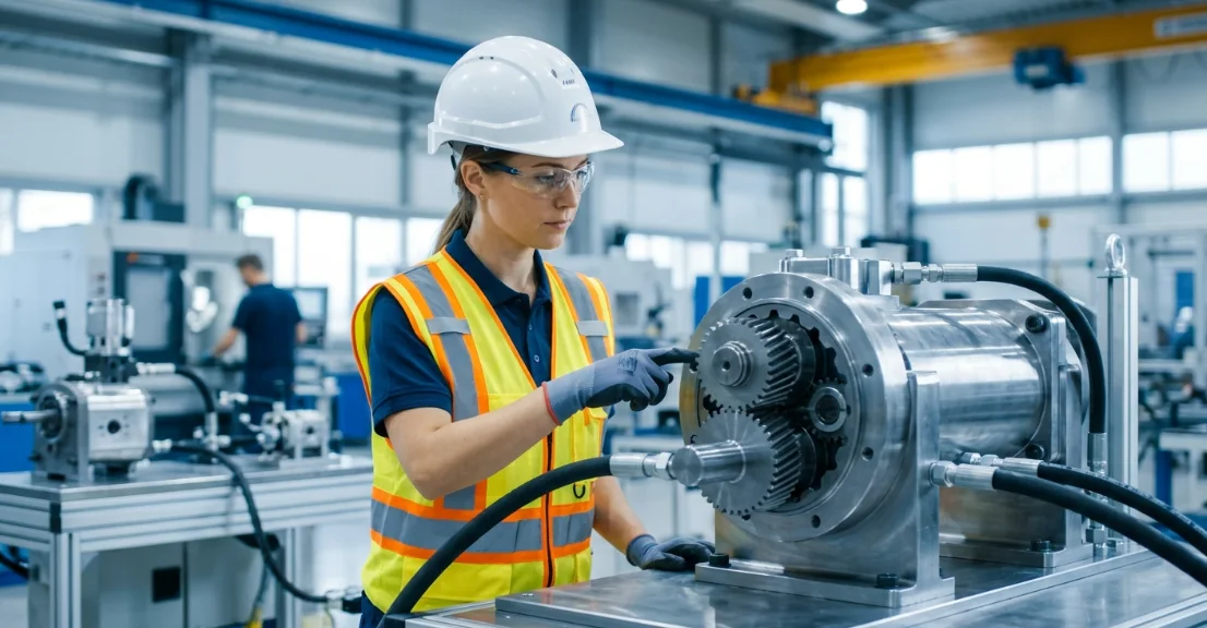
Gear pumps and hydraulic gear motors share an almost identical internal architecture. The difference between them comes down to which end receives energy and which end delivers it.
Once you grasp how these devices can pull double duty, you open the door to smarter system layouts, lower costs, and easier upkeep. In the sections ahead, we'll walk through how a hydraulic motor conversion actually works, what happens when you push flow backward through a gear pump, and why a positive displacement rotary actuator can handle motion in both directions.
Fundamental Operating Principle — Pump vs. Motor Mode
How a Gear Pump Generates Flow
In pump mode, an external prime mover such as an electric motor or engine spins the drive shaft. That shaft rotates a pair of meshing gears inside a tightly fitted housing.
As the gear teeth unmesh on the inlet side, expanding cavities create a low-pressure zone that draws fluid in. The fluid is then carried in the spaces between gear teeth and the casing wall toward the outlet port.
When the teeth re-mesh on the discharge side, they squeeze the trapped fluid out under pressure. This is the fundamental action of every positive displacement rotary actuator operating in pump mode — fixed volumes of fluid are displaced per revolution regardless of system pressure.
Pressure Driven Gear Rotation — The Reversal Concept
Now reverse the energy input. Instead of spinning the shaft mechanically, supply pressurized fluid to what was previously the discharge port. That high-pressure fluid pushes against the exposed faces of the gear teeth.
Because the meshing zone seals one side from the other, a pressure differential develops across each gear. This imbalance generates a net force on the gear teeth, producing torque and causing the gears to rotate — the essence of pressure driven gear rotation.
The shaft, no longer receiving torque, now delivers it to an external load. The device has become a hydraulic motor without a single internal component changing.
Energy Conversion Comparison Table
| Parameter | Gear Pump Mode | Hydraulic Motor Mode |
|---|---|---|
| Input Energy | Mechanical (shaft) | Hydraulic (pressure/flow) |
| Output Energy | Hydraulic (flow) | Mechanical (torque) |
| Driving Force | External prime mover | Pressurized fluid |
| Shaft Function | Receives torque | Delivers torque |
| Flow Direction | Internal to external | External to internal |
Hydraulic Motor Conversion Principle — What Physically Happens
Pressure Differential Across Gear Teeth
The hydraulic motor conversion principle hinges on one physical reality: unequal pressure acting on opposite sides of each gear tooth. High-pressure fluid enters one side of the gear cavity while the meshing zone blocks it from reaching the low-pressure outlet side.
This pressure imbalance creates a tangential force on every exposed tooth face. The cumulative effect across all teeth in the pressure zone produces a continuous net torque on both gears.
The drive gear transmits this torque through the output shaft to the connected load. The idler gear rotates in the opposite direction, maintained in sync by the meshing contact.
Gear Pump Reverse Flow Operation Mechanics
Gear pump reverse flow operation does not require physically reversing the gears. It simply means fluid enters through what was the outlet port and exits through what was the inlet port.
The pressurized fluid fills the expanding cavities as teeth unmesh on the high-pressure side. It then rides around the periphery in the tooth spaces, exactly as it would in pump mode but driven by external pressure rather than shaft rotation.
As the teeth re-mesh on the low-pressure side, fluid is expelled at reduced pressure. No structural modification is needed — the geometry that displaces fluid in pump mode accepts displaced fluid in motor mode with equal effectiveness.
Role of Trapped Volume and Sealing Zones
Tight clearances between gear tooth tips and the internal casing wall form dynamic sealing zones. These clearances, typically 0.025 to 0.050 mm in quality units, prevent high-pressure fluid from short-circuiting directly to the low-pressure side.
The meshing zone itself creates another critical seal. As teeth interlock, they trap small volumes of fluid that must be relieved through pressure-balancing grooves to avoid noise and pressure spikes.
In motor mode, maintaining these sealing zones is essential for volumetric efficiency. Any increase in clearance due to wear directly reduces the percentage of input flow that contributes to useful shaft rotation.
Design Factors That Enable Bidirectional Operation
Bidirectional Hydraulic Pump Motor Compatibility
Not every gear pump transitions seamlessly into motor duty. Units designed as a bidirectional hydraulic pump motor incorporate specific features that support energy flow in either direction.
Symmetric porting allows equal performance regardless of which port receives pressure. Balanced bearing designs handle radial loads from either rotation direction without premature wear.
Shaft seals rated for both internal pressure and external contamination ensure reliable operation. Additionally, case drain ports manage internal leakage that would otherwise pressurize the housing and blow seals during sustained motor operation.
Internal vs. External Gear Configurations
| Feature | External Gear Motor | Internal Gear Motor |
|---|---|---|
| Torque Density | Moderate | Higher |
| Speed Range | High RPM capable | Lower RPM, smoother |
| Noise Level | Higher | Lower |
| Reversibility Ease | Excellent | Good |
| Typical Application | Conveyors, fans | Injection molding, steering |
External gear motors use two identical spur gears meshing side by side. Their symmetric design makes them naturally suited to bidirectional rotation and easy to manufacture at scale.
Internal gear motors feature a smaller gear rotating inside a larger ring gear. The crescent-shaped sealing element between them provides smoother flow characteristics and quieter operation, though at the cost of slightly more complex construction.
Limitations When Using a Pump as a Motor
Running a standard gear pump in motor mode introduces several performance compromises. Volumetric efficiency drops because internal leakage paths that were acceptable in pump duty become more significant under sustained pressure loading.
Bearing loads differ between modes. In pump mode, pressure forces push gears apart in a predictable pattern. In motor mode, load vectors shift, potentially exceeding the bearing capacity of units not designed for dual service.
Without a proper case drain line, internal leakage accumulates in the housing. This pressurizes the case, overloads shaft seals, and can cause catastrophic failure during extended motor operation. Purpose-built gear motors always include drain provisions.
Positive Displacement Rotary Actuator — Performance Characteristics
Torque and Speed Calculations
Output torque from a gear motor depends on displacement and pressure differential. The governing formula is:
T = (D × ΔP) / (2π × 1000)
Where T is torque in Nm, D is displacement in cc/rev, and ΔP is pressure drop across the motor in bar. This relationship shows that torque is independent of speed — a defining characteristic of the positive displacement rotary actuator.
Shaft speed relates directly to input flow rate:
n = Q / D
Where n is speed in rev/s, Q is flow rate in cc/s, and D is displacement in cc/rev. Increasing flow raises speed proportionally while torque remains governed by pressure alone.
Efficiency Metrics Table
| Efficiency Type | Typical Pump Value | Typical Motor Value | Key Loss Source |
|---|---|---|---|
| Volumetric | 90–95% | 85–93% | Internal leakage |
| Mechanical | 85–92% | 80–90% | Friction, bearing drag |
| Overall | 78–88% | 70–84% | Combined losses |
The efficiency gap between pump and motor modes stems from the different loading conditions. Motor operation subjects internal components to continuous high-pressure exposure on one side, increasing cross-gear leakage and bearing friction simultaneously.
Temperature also plays a larger role in motor mode. As fluid heats up, viscosity drops, and internal leakage increases further. Proper thermal management becomes critical for maintaining acceptable efficiency in sustained motor applications.
Practical Applications of Gear Motors
Gear motors excel in applications requiring moderate torque at reasonable speeds with compact packaging. Their simplicity and ruggedness make them workhorses across multiple industries.
Common applications include:
- Winch drives — reliable torque for cable pulling and lifting operations
- Wheel drives — compact power for mobile equipment and small vehicles
- Mixer and agitator drives — consistent rotation for blending processes
- Conveyor drives — steady speed for material handling systems
- Agricultural equipment — seed drills, spreaders, and auger drives
- Fan and blower drives — cooling systems in harsh environments
The positive displacement rotary actuator format ensures these applications receive predictable output regardless of load variations, a key advantage over centrifugal or variable-displacement alternatives in fixed-duty scenarios.
Key Conditions for Successful Pump-to-Motor Operation
Minimum Pressure and Flow Requirements
Every gear motor has a minimum pressure threshold below which it will not start rotating. This breakaway pressure must overcome internal friction from seals, bearings, and gear mesh contact before any useful rotation begins.
Typical breakaway pressure for external gear motors ranges from 15 to 35 bar depending on displacement size and seal type. Once rotation begins, running pressure can be somewhat lower due to reduced static friction.
Minimum flow requirements also exist. Below a certain flow rate, internal leakage consumes most of the input volume, and the motor either stalls or rotates erratically. Manufacturers specify minimum speed ratings — typically 200 to 500 RPM — to ensure stable operation.
System Integration Considerations
Successful motor-mode operation demands attention to several system-level details that pump installations may not require.
Case drain provisions: A dedicated low-pressure return line from the motor housing to the reservoir prevents internal pressure buildup. This line should be sized generously and routed to avoid back-pressure.
Filtration: Motor-mode operation is more sensitive to contamination because particles can wedge in the tight clearances that maintain volumetric efficiency. A minimum of 10-micron filtration upstream of the motor is recommended.
Thermal management: Continuous motor duty generates more heat than intermittent pump duty. System cooling capacity must account for the lower overall efficiency and higher sustained heat rejection.
Circuit design: Cross-port relief valves protect against pressure spikes during load reversals. Anti-cavitation check valves prevent damage if the motor overruns its supply flow during deceleration.
Frequently Asked Questions (FAQ)
Can any gear pump work as a hydraulic motor?
Most external gear pumps can function as motors, but purpose-built units offer better efficiency, proper shaft sealing, and appropriate bearing support for sustained motor duty. Using a standard pump in continuous motor service without verifying drain provisions and bearing ratings risks premature failure.
What is the main difference between a gear pump and a gear motor?
The core mechanism is identical — the difference lies in energy direction. A pump converts mechanical input to fluid flow, while a motor converts pressurized flow back to shaft rotation. Purpose-built motors include design refinements for sustained pressure loading, but the operating geometry remains the same.
Why is motor-mode efficiency lower than pump-mode efficiency?
Additional internal leakage paths under sustained pressure loading and higher bearing side-loads reduce both volumetric and mechanical efficiency during motor operation. The continuous high-pressure exposure on one side of the gears increases cross-port leakage compared to the more balanced pressure distribution in pump mode.
Does gear pump reverse flow operation damage the unit?
Not inherently. Units designed for bidirectional hydraulic pump motor service handle reverse flow without damage. However, unidirectional pumps may have seal lip orientations or bearing preload directions that are incompatible with reverse operation. Always verify manufacturer specifications before running a pump in reverse flow.
What controls the speed of a gear motor?
Flow rate determines speed. Increasing volumetric flow raises RPM proportionally, while pressure differential governs available torque output. This independent control of speed and torque through separate hydraulic variables is a fundamental advantage of positive displacement motor systems.



