
If your hydraulic gear pump goes down, the costs add up fast — we're talking hundreds of dollars a minute in lost production. Noisy operation, dropping pressure, fluid leaking where it shouldn't — these are problems most of us have run into at some point. The good news is that with the right diagnostic steps and a bit of hands-on know-how, you can often fix the issue yourself, skip the hefty replacement bill, and get everything running again without waiting on a service call.
This technical manual provides a comprehensive, systematic methodology for gear pump restoration, encompassing diagnostic assessment of failure modes through final reassembly and performance verification. Utilizing appropriate instrumentation, a precision-engineered gear pump rebuild kit, and adherence to established procedural protocols, the majority of gear pump rehabilitations can be executed within a single operational shift, thereby eliminating the necessity for outsourced overhaul services and their associated expenditures.
Understanding Hydraulic Gear Pump Failures
How a Hydraulic Gear Pump Works
A hydraulic gear pump converts mechanical energy into hydraulic flow by trapping fluid between meshing gear teeth and the pump housing. As the gears rotate, fluid is carried from the inlet (suction) side to the outlet (pressure) side, creating a consistent flow that powers downstream actuators and motors.
External gear pumps use two interlocking spur gears, while internal gear pumps use a smaller gear rotating inside a larger ring gear. In both designs, tight clearances between the gears, wear plates, and housing bore are critical for maintaining volumetric efficiency.
When these clearances increase due to wear or damage, the pump loses its ability to maintain pressure and flow. Understanding this basic operating principle helps you pinpoint exactly where failures originate during hydraulic pump troubleshooting.
Common Symptoms of a Failing Gear Pump
The earliest warning sign is usually increased noise. A healthy gear pump produces a steady hum, while a failing unit develops a whining, grinding, or knocking sound that indicates internal damage or cavitation.
Pressure drop under load is another telltale symptom. If your system struggles to reach or maintain its rated operating pressure, internal leakage past worn gears or degraded gear pump wear plates is likely the cause.
External fluid leaks around the shaft seal or housing joints signal that hydraulic pump seal replacement is overdue. Overheating, erratic cylinder movement, and sluggish actuator response all point to a pump that needs immediate attention before catastrophic failure occurs.
Root Causes of Gear Pump Damage
Understanding what caused the failure is essential before starting any repair. Fixing symptoms without addressing root causes leads to repeat failures and wasted rebuild kits.
| Cause | Symptom | Affected Component |
|---|---|---|
| Contaminated fluid | Scoring, abrasion | Gears, wear plates, housing |
| Cavitation | Whining noise, pitting | Gear teeth, inlet port |
| Seal degradation | External leaks | Shaft seals, O-rings |
| Misalignment | Vibration, premature wear | Bearings, shaft |
| Overpressure | Cracking, blowouts | Housing, end caps |
Contaminated hydraulic fluid is the number one killer of gear pumps. Particles as small as 10 microns act as abrasive compounds that accelerate wear on every internal surface. Always investigate fluid condition as part of your hydraulic pump troubleshooting process.
Tools and Parts Needed for Gear Pump Repair
Essential Tools Checklist
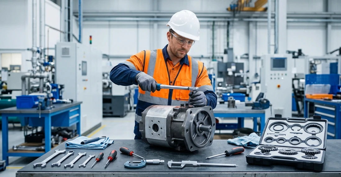
Having the right tools on hand before disassembly prevents delays and reduces the risk of damaging components during the repair process.
- Torque wrench — Accurate to ±2% for proper bolt tightening
- Snap ring pliers — Internal and external types for retaining rings
- Dial indicator with magnetic base — For measuring shaft runout and gear clearances
- Soft-jaw vise — Holds the pump body without marring machined surfaces
- Cleaning solvent and lint-free rags — For degreasing all components before inspection
- Feeler gauge set — For checking axial and radial clearances
- Seal installation tools — Prevents damage during hydraulic pump seal replacement
- Digital caliper or micrometer — For measuring gear tooth thickness and bore diameter
Avoid using standard steel-jaw vises or channel-lock pliers on pump components. Aluminum housings and precision-ground surfaces are easily damaged by improper clamping.
Gear Pump Rebuild Kit Components
A quality gear pump rebuild kit contains all the wear components needed to restore your pump to factory specifications. Purchasing a complete kit is more cost-effective and reliable than sourcing individual seals and plates.
| Kit Component | Function |
|---|---|
| Shaft seals | Prevent external leakage |
| Gear pump wear plates | Restore volumetric efficiency |
| Thrust plates | Maintain axial clearance |
| O-rings and gaskets | Seal housing joints |
| Bushings/bearings | Support gear shafts |
Always match the rebuild kit to your exact pump model and series number. Even pumps that look identical externally may have different internal dimensions or seal configurations between production runs.
Step-by-Step Hydraulic Gear Pump Repair Process
Step 1 — Safe Removal and Disassembly
Safety comes first. Depressurize the entire hydraulic system by cycling actuators with the engine off, then verify zero pressure at the gauge before disconnecting any lines.
Drain the fluid from the pump and adjacent lines into a clean container. Inspect the drained fluid for metal particles, discoloration, or a burnt smell — these provide clues about the failure mode you'll be addressing.
Tag and photograph all hose connections before removal. Mark the pump mounting orientation and coupling alignment so reinstallation goes smoothly. Remove the pump from its mount and transport it to a clean workbench.
Disassemble the pump in a systematic order: remove end cap bolts, separate the end caps from the housing, then carefully extract the gears and wear plates. Keep components organized and note their orientation — many wear plates and thrust plates are directional.
Step 2 — Inspection and Damage Assessment
Clean all components thoroughly with solvent and inspect each one under good lighting. This step determines whether a repair is viable or if the pump needs replacement.
Measure gear tooth thickness with a micrometer and compare to manufacturer specifications. Wear beyond 0.05 mm typically means the gears need replacement. Check for pitting, chipping, or scoring on the tooth faces and tips.
Inspect the housing bore for scoring or out-of-round conditions using an inside micrometer. Light polishing marks are normal, but deep grooves indicate contamination damage. Examine gear pump wear plates for scoring patterns — uniform wear is repairable, but deep channels mean replacement is necessary.
Check shaft journals for wear grooves at the seal contact area. A groove deeper than 0.1 mm will prevent new seals from seating properly and may require a shaft sleeve or pump replacement.
Step 3 — Hydraulic Pump Seal Replacement
Remove old shaft seals carefully using a seal pick or small pry bar. Avoid scratching the seal bore surface, as any damage here will cause the new seal to leak immediately.
Clean the seal grooves and bores completely, removing any old adhesive or debris. Inspect the seal surfaces for corrosion or pitting that could compromise the new seal's ability to maintain contact.
Install new seals with the correct orientation — the lip must face the pressurized side. Use a proper seal driver or installation sleeve to press seals in squarely without cocking. Lubricate the seal lip with clean hydraulic fluid before installation to prevent dry-start damage.
Replace all O-rings and gaskets from the gear pump rebuild kit, even those that appear undamaged. Reusing old elastomers is the most common cause of post-repair leaks and undermines the entire hydraulic pump seal replacement effort.
Step 4 — Replacing Wear Plates and Bearings
Scored gear pump wear plates are the primary cause of volumetric efficiency loss. Remove the old plates and clean the mating surfaces in the housing thoroughly.
Install new wear plates with the correct side facing the gears. Most plates have a pressure-loaded side (often marked with an arrow or identified by a smoother finish) that must face the gear faces to maintain the pressure-balancing function.
Press new bushings into the housing and end caps using an arbor press. Ensure they seat fully and squarely — a cocked bushing will cause shaft binding and rapid failure. After installation, verify the inside diameter matches specifications using a telescoping gauge.
Check axial clearance by placing the gears between new wear plates and measuring the gap with a feeler gauge. Typical clearance is 0.025–0.075 mm, but always refer to your pump's service manual for exact specifications.
Step 5 — Reassembly and Torque Specifications
Reassemble the pump in reverse order of disassembly. Lubricate all internal components with clean hydraulic fluid during assembly to prevent dry starts and ensure immediate lubrication on first rotation.
Verify that gears rotate freely by hand before installing end caps. Any binding indicates misaligned bushings or incorrect wear plate installation that must be corrected before proceeding.
| Component | Torque Spec (typical) | Note |
|---|---|---|
| End cap bolts | 25–35 Nm | Cross-pattern sequence |
| Port fittings | 20–30 Nm | Use new O-rings |
| Mounting bolts | 40–55 Nm | Check alignment |
Always tighten end cap bolts in a cross-pattern sequence to ensure even clamping pressure. Uneven torque distorts the housing and creates internal clearance problems that reduce pump performance.
Important: These torque values are general guidelines. Always consult your specific pump manufacturer's service manual for exact specifications, as values vary significantly between brands and pump sizes.
Step 6 — Priming, Reinstallation, and Testing
Fill the pump with clean hydraulic fluid through the inlet port before reinstallation. This primes the pump and prevents cavitation damage during initial startup. Rotate the shaft by hand several times to distribute fluid across all internal surfaces.
Reinstall the pump on its mount, ensuring proper coupling alignment. Misalignment is a leading cause of premature bearing and seal failure — use a dial indicator to verify alignment within 0.05 mm.
Reconnect all hydraulic lines using new O-rings on port fittings. Bleed air from the system by loosening the highest-point fitting and running the pump at low speed until bubble-free fluid appears.
Run the pump at low pressure (no load) for 5–10 minutes while monitoring for leaks, unusual noise, and temperature rise. Gradually increase pressure to operating levels and verify flow rate meets specifications.
Hydraulic Pump Troubleshooting After Repair
Post-Repair Performance Benchmarks
After completing the repair, systematic testing confirms the pump is operating within acceptable parameters. Document these readings as a baseline for future hydraulic system maintenance comparisons.
| Parameter | Acceptable Range | Action if Out of Spec |
|---|---|---|
| Flow rate | ±5% of rated | Re-check internal clearances |
| Operating pressure | Stable at set PSI | Inspect relief valve |
| Temperature | Below 82°C (180°F) | Check fluid viscosity |
| Noise level | No cavitation whine | Verify inlet restriction |
If flow rate is low but pressure is stable, the issue is likely internal leakage past wear plates or gears. If pressure fluctuates, look at the relief valve or check for air entrainment in the system.
Allow the pump to run for at least one hour at operating conditions before declaring the repair successful. Some issues only manifest once components reach operating temperature and thermal expansion takes effect.
Ongoing Hydraulic System Maintenance Tips
Preventive hydraulic system maintenance dramatically extends the interval between repairs. The single most impactful practice is maintaining clean fluid — contamination causes over 80% of hydraulic component failures.
- Fluid analysis: Sample and test hydraulic fluid every 500 operating hours for particle count, water content, and viscosity
- Filter replacement: Change return-line and pressure filters at manufacturer-recommended intervals or when differential pressure indicators trigger
- Alignment checks: Verify pump-to-motor coupling alignment every 2,000 hours or after any maintenance that disturbs the mounting
- Temperature monitoring: Track operating temperature trends — a gradual increase signals declining efficiency
- Inlet condition: Inspect suction strainers and hoses for collapse or restriction that causes cavitation
Keep a maintenance log for each pump in your system. Tracking hours, fluid changes, and performance readings helps you predict failures before they cause unplanned downtime.
When to Repair vs. Replace Your Gear Pump
Cost-Benefit Decision Matrix
Not every pump is worth repairing. Use this decision matrix to determine whether a rebuild makes economic sense for your specific situation.
| Factor | Repair | Replace |
|---|---|---|
| Housing damage | Minor scoring only | Cracked or warped |
| Gear tooth condition | Light wear | Broken or heavily pitted |
| Pump age | Under 10,000 hours | Beyond service life |
| Downtime tolerance | Flexible | Critical operation |
| Parts availability | Rebuild kit available | Obsolete model |
As a general rule, if repair costs exceed 50–60% of a new pump's price, replacement is the better investment. A new pump comes with a warranty and full service life ahead of it.
However, lead times matter. If a replacement pump has a 6–8 week delivery window and a gear pump rebuild kit is available immediately, a repair that gets you running today may be worth more than a new unit next month. Factor in the total cost of downtime when making your decision.
For critical applications where unplanned downtime is unacceptable, consider keeping a rebuilt spare pump on the shelf. This gives you the best of both worlds — immediate swap capability with the cost savings of rebuilding units during scheduled maintenance windows.
FAQ
How long does it take to repair a hydraulic gear pump?
Most repairs take 2–4 hours once parts are on hand, depending on damage severity and your familiarity with the specific pump model. First-time repairs may take longer due to the learning curve of disassembly sequences and clearance measurements. Having a clean workspace, proper tools, and a complete gear pump rebuild kit ready before starting minimizes total repair time.
Can I repair a hydraulic gear pump without a rebuild kit?
While it's technically possible to replace only individual failed components, a gear pump rebuild kit ensures all wear components are replaced together for reliable results. Seals, wear plates, and bushings wear at similar rates, so replacing only one component often leads to a second failure shortly after. The cost difference between individual parts and a complete kit is minimal compared to the labor of a repeat teardown.
What causes a hydraulic gear pump to lose pressure after repair?
Improper seal installation, air in the system, or incorrect wear plate orientation are the most common post-repair issues that cause pressure loss. Verify that wear plate pressure-loaded faces are oriented toward the gears, all seals are installed with lips facing the correct direction, and the system is fully bled of air. Also confirm that the relief valve hasn't been inadvertently adjusted during the repair process.
How often should hydraulic gear pumps be serviced?
Follow a hydraulic system maintenance schedule — typically every 2,000–4,000 operating hours or per manufacturer guidelines. Service intervals should include fluid sampling, filter changes, and external inspection for leaks or unusual noise. Pumps operating in harsh environments with temperature extremes, high contamination risk, or continuous duty cycles may require more frequent attention.
Is hydraulic pump troubleshooting possible without specialized tools?
Basic diagnosis including identifying noise patterns, spotting external leaks, and taking pressure readings can be done with standard gauges and visual inspection. However, precision repair requires proper measurement instruments such as micrometers, dial indicators, and feeler gauges to verify clearances and wear dimensions. Attempting a rebuild without these tools risks assembling a pump that fails prematurely due to undetected out-of-spec conditions.



