

Every second, thousands of aluminum hydraulic gear pumps silently power the machinery that builds our world — from compact forklifts to massive agricultural equipment. Yet most operators never understand why this lightweight powerhouse outperforms heavier alternatives at a fraction of the cost.
Whether you're specifying a new gear pump fluid power system or troubleshooting an existing one, understanding the aluminum hydraulic gear pump inside and out gives you a decisive edge. This guide covers everything from operating principles and pressure ratings to selection criteria and maintenance schedules, so you can make confident, informed decisions.
What Is an Aluminum Hydraulic Gear Pump?
Core Definition and Operating Principle
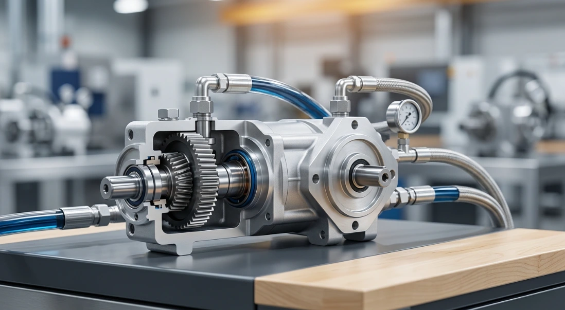
An aluminum hydraulic gear pump is a positive-displacement device that uses two meshing gears rotating inside a precision-machined aluminum housing to move hydraulic fluid. As the gears unmesh at the inlet side, they create a vacuum that draws fluid into the expanding cavities between the gear teeth and the housing wall.
The trapped fluid is then carried around the periphery of each gear toward the outlet port. As the gears re-mesh on the discharge side, fluid is forced out under pressure, generating the continuous flow that powers hydraulic cylinders, motors, and actuators downstream.
This simple yet effective mechanism makes the hydraulic pump aluminum body design one of the most reliable fluid power solutions available. With fewer moving parts than piston or vane pumps, gear pumps deliver consistent performance with minimal complexity.
Key Components Breakdown
Understanding each component helps you diagnose issues faster and select the right replacement parts. Here's what's inside a typical aluminum hydraulic gear pump:
| Component | Material | Function |
|---|---|---|
| Housing/Body | Cast Aluminum Alloy | Lightweight structural enclosure |
| Drive Gear | Hardened Steel | Primary rotation element |
| Idler Gear | Hardened Steel | Secondary meshing element |
| Bearing Plates | Bronze/Aluminum | Support and sealing surfaces |
| Shaft Seal | Nitrile/Viton | Prevents external leakage |
| Port Fittings | Aluminum/Steel | Inlet and outlet connections |
The aluminum alloy housing is typically die-cast or gravity-cast to achieve tight tolerances. Internal gear-to-housing clearances often measure just 0.001–0.003 inches, which is critical for maintaining volumetric efficiency under pressure.
External vs. Internal Gear Pump Designs
In aluminum gear pump hydraulic systems, two primary gear configurations exist. External gear pumps use two identical spur gears meshing side by side, with both gear shafts supported by bearings in the housing end plates. This is the most common design for mobile and light industrial applications.
Internal gear pumps feature a larger external gear (rotor) with internal teeth that mesh with a smaller internal gear (idler). A crescent-shaped separator divides the inlet and outlet zones. Internal designs run quieter and handle higher viscosity fluids, but external gear pumps offer better pressure capability and simpler construction.
For most aluminum-bodied applications in the 2,500–3,500 PSI range, external gear designs dominate due to their cost-effectiveness and proven durability in gear pump fluid power circuits.
Why Aluminum? Material Advantages in Gear Pump Fluid Power
Weight-to-Strength Ratio Benefits
Aluminum's density sits at roughly one-third that of cast iron or steel. In practical terms, a hydraulic pump aluminum body can reduce pump weight by up to 60% compared to an equivalent cast iron unit. For a 14 cc/rev pump, that might mean 2.5 kg versus 6 kg installed weight.
This weight reduction compounds across mobile hydraulic systems where every kilogram affects fuel consumption, payload capacity, and structural loading. On aerial platforms and compact equipment, lighter pumps also reduce vibration-induced fatigue on mounting brackets and drive couplings.
Thermal Conductivity and Heat Dissipation
Aluminum conducts heat approximately three times faster than cast iron. In continuous-duty hydraulic gear motor aluminum applications, this means the pump body itself acts as a heat sink, radiating thermal energy away from the gear mesh zone and bearings.
Better heat dissipation translates directly to longer seal life, more stable fluid viscosity, and reduced risk of thermal breakdown in the hydraulic oil. Systems running aluminum pumps often require smaller oil coolers or can operate with reduced reservoir volumes.
Corrosion Resistance and Longevity
Aluminum naturally forms a protective oxide layer that resists moisture-driven corrosion. This makes aluminum gear pumps well-suited for outdoor mobile equipment, marine environments, and agricultural machinery exposed to rain, humidity, and chemical spray.
While aluminum doesn't match stainless steel in extreme chemical environments, it significantly outperforms cast iron in typical field conditions. Many manufacturers also apply anodized or chromate conversion coatings for additional protection.
Aluminum vs. Cast Iron vs. Steel Pumps
Choosing the right pump body material depends on your application's pressure demands, weight constraints, and operating environment. This comparison highlights where each material excels:
| Feature | Aluminum Body | Cast Iron | Steel |
|---|---|---|---|
| Weight | Low | High | High |
| Cost | Moderate | Moderate | High |
| Max Pressure (PSI) | 3,000–4,000 | 4,000–5,000 | 5,000+ |
| Heat Dissipation | Excellent | Good | Fair |
| Corrosion Resistance | Good | Poor | Moderate |
| Typical Applications | Mobile/Light Industrial | Heavy Industrial | Extreme Duty |
For the majority of mobile hydraulic and light-to-medium industrial applications, aluminum delivers the optimal balance of performance, weight, and cost. Cast iron and steel become necessary only when sustained pressures exceed 4,000 PSI or when extreme mechanical abuse is expected.
Performance Specifications and Pressure Ratings
Aluminum Hydraulic Pump Pressure Ranges
Standard aluminum hydraulic pump pressure ratings fall between 2,500 and 3,500 PSI for continuous operation. Intermittent or peak pressure ratings typically reach 4,000 PSI, though these should represent brief transient spikes rather than sustained operating conditions.
Smaller displacement pumps generally tolerate higher pressures because the internal forces acting on the housing and bearings are proportionally lower. As displacement increases, maximum rated pressure typically decreases to maintain acceptable housing stress and bearing loads.
Always reference the specific manufacturer's pressure-flow curve for your pump model. Operating consistently above rated pressure accelerates wear on bearing plates, increases internal leakage, and can lead to catastrophic housing failure.
Flow Rate and Displacement Options
Displacement determines how much fluid the pump moves per revolution, directly controlling system flow rate at a given drive speed. Here are common displacement sizes and their output characteristics:
| Displacement (cc/rev) | Typical Flow @ 1500 RPM (LPM) | Max Continuous Pressure (PSI) |
|---|---|---|
| 4 | 6 | 3,500 |
| 8 | 12 | 3,200 |
| 14 | 21 | 3,000 |
| 22 | 33 | 2,800 |
| 39 | 58.5 | 2,500 |
These figures assume standard volumetric efficiency of approximately 90–93%. Actual delivered flow decreases as system pressure increases due to internal slip across the gear faces and bearing plates.
Speed Limitations and Efficiency Curves
Most aluminum gear pumps operate optimally between 1,000 and 3,000 RPM. Below 500 RPM, volumetric efficiency drops significantly as internal leakage becomes a larger percentage of total displacement. Above 3,500 RPM, cavitation risk increases and mechanical efficiency suffers from accelerated wear.
Peak overall efficiency (volumetric × mechanical) typically occurs at moderate pressure and mid-range speed — often around 2,000 PSI and 1,800 RPM for a standard aluminum unit. At this sweet spot, total efficiency commonly reaches 85–90%.
Running an aluminum gear pump hydraulic system at its efficiency peak reduces heat generation, extends component life, and maximizes the useful power delivered to actuators.
Applications of Aluminum Hydraulic Gear Pumps
Mobile Hydraulic Equipment
The lightweight nature of aluminum gear pumps makes them the default choice for mobile hydraulic systems. Forklifts, aerial work platforms, compact excavators, skid-steer loaders, and utility vehicles all rely on these pumps for their lift, tilt, and steering circuits.
In mobile applications, the reduced weight directly improves vehicle payload capacity and fuel efficiency. The compact form factor also simplifies packaging in tight engine compartments where space is at a premium.
Agricultural Machinery
Tractors, combine harvesters, sprayers, and hydraulic implement systems depend on aluminum gear pumps for reliable power delivery in demanding field conditions. These pumps handle the constant cycling between loaded and unloaded states that agricultural work demands.
The corrosion resistance of aluminum is particularly valuable in agricultural settings where pumps face exposure to fertilizers, pesticides, and moisture. Many tractor auxiliary hydraulic circuits use tandem or triple aluminum gear pump assemblies to power multiple functions simultaneously.
Industrial and Manufacturing Systems
Log splitters, hydraulic presses, power packs, conveyor tensioning systems, and machine tool lubrication circuits all use aluminum gear pumps. In these applications, the pump's simplicity and low maintenance requirements minimize downtime.
Small hydraulic power units built with aluminum gear pumps serve as the backbone of countless industrial automation systems. Their fixed-displacement output pairs well with simple pressure-relief valve circuits for basic force and motion control.
Marine and Automotive Uses
Marine trim tab actuators, hydraulic steering systems, and boat trailer winches commonly use compact aluminum gear pumps. The corrosion-resistant housing withstands saltwater environments better than cast iron alternatives.
In automotive applications, aluminum gear pumps serve in transmission lubrication circuits, power steering systems, and aftermarket hydraulic suspension setups. Their ability to deliver consistent flow at varying engine speeds makes them reliable across the RPM range.
Selection Criteria for the Right Aluminum Gear Pump Hydraulic System
Matching Displacement to Load Requirements
Start by calculating the flow rate your actuators need. For cylinders, multiply bore area by required extension speed. For hydraulic motors, multiply displacement by desired RPM. Then divide total required flow by your available drive speed to determine minimum pump displacement.
Always add a 10–15% margin above calculated minimum to account for volumetric efficiency losses and system leakage. Undersizing the pump forces the system to operate at maximum capacity continuously, accelerating wear and generating excess heat.
Shaft Configuration and Mounting Options
Aluminum gear pumps are available in SAE A (two-bolt), SAE B (two-bolt, larger), and SAE C (four-bolt) mounting flanges. The mounting pattern must match your bell housing, PTO adapter, or electric motor coupling.
Shaft options include keyed cylindrical, splined, and tapered configurations. Keyed shafts suit jaw couplings and direct motor drives. Splined shafts are standard for PTO connections on mobile equipment. Verify shaft rotation direction — most pumps are available in clockwise or counterclockwise variants.
Port Orientation and Sizing
Inlet and outlet port positions vary by manufacturer and model series. Common configurations include rear ports, side ports, and top/bottom arrangements. Select the orientation that minimizes hose routing complexity and avoids sharp bends that restrict flow.
Inlet port sizing is critical. An undersized inlet creates a restriction that causes cavitation, noise, and premature failure. As a rule, inlet lines should be at least one size larger than the outlet and kept as short as possible with minimal fittings.
Fluid Compatibility Considerations
Standard aluminum gear pumps are designed for petroleum-based hydraulic fluids in the ISO VG 32–68 viscosity range. Operating viscosity at working temperature should remain between 16 and 100 cSt for optimal film strength and efficiency.
If your application requires fire-resistant fluids, biodegradable oils, or synthetic formulations, verify compatibility with all seal materials and the aluminum housing itself. Some phosphate-ester fluids and high-water-content fluids can attack aluminum alloys or degrade standard nitrile seals.
Installation and Maintenance Best Practices
Proper Priming and Start-Up Procedures
Never start an aluminum gear pump dry. Before initial commissioning, fill the pump housing with clean hydraulic fluid through the uppermost port. This pre-priming ensures immediate lubrication of gears and bearings during the critical first seconds of operation.
During first start-up, run the pump at low pressure and reduced speed for several minutes. This allows trapped air to purge from the system and lets bearing surfaces develop their initial wear pattern without excessive loading. Monitor for unusual noise or temperature rise during this break-in period.
Preventive Maintenance Schedule
Consistent maintenance is the single most effective way to maximize pump life. Follow this schedule to catch problems before they cause unplanned downtime:
| Interval | Action |
|---|---|
| Daily | Check fluid level and inspect for leaks |
| 250 Hours | Replace return line filter |
| 500 Hours | Analyze fluid condition |
| 1,000 Hours | Inspect inlet strainer and seals |
| 2,000 Hours | Full pump inspection and wear assessment |
Fluid cleanliness is the number one factor in gear pump longevity. Maintain ISO 18/16/13 cleanliness or better. Contaminated fluid accelerates abrasive wear on gear tooth surfaces and bearing plates, leading to increased internal leakage and reduced efficiency.
Common Failure Modes and Troubleshooting
Cavitation: A high-pitched whining or rattling noise at the inlet side indicates the pump is starving for fluid. Check for restricted inlet lines, clogged strainers, collapsed suction hoses, or fluid viscosity that's too high for the operating temperature.
Overheating: If the pump housing exceeds 180°F (82°C), investigate excessive system pressure, relief valve set too high, or insufficient reservoir cooling capacity. Prolonged overheating degrades seals and accelerates fluid breakdown.
Seal failure: External leakage at the shaft seal typically results from misalignment, excessive side loading, or contaminated fluid scoring the shaft surface. Replace the seal and address the root cause to prevent recurrence.
Excessive noise: Beyond cavitation, noise can indicate worn gears, bearing plate wear, or misalignment between the pump shaft and prime mover. Coupling inspection and a flow test at rated pressure will help isolate the source.
Frequently Asked Questions
What is the maximum pressure an aluminum hydraulic gear pump can handle?
Most aluminum body pumps operate continuously between 2,500–3,500 PSI, with intermittent peaks up to 4,000 PSI depending on displacement and manufacturer specifications. Smaller displacement models generally support higher pressures due to reduced internal forces on the housing. Always reference the specific model's datasheet for exact aluminum hydraulic pump pressure limits.
How long does an aluminum gear pump typically last?
With proper maintenance and clean fluid, expect 5,000–10,000 operating hours in standard mobile applications. Industrial applications with controlled environments and consistent maintenance programs often achieve the upper end of this range. Fluid cleanliness and correct system pressure are the two biggest factors influencing service life.
Can aluminum gear pumps handle bi-directional rotation?
Many models support bi-directional operation, but port configuration and internal drain provisions must be verified for reverse-flow use. Some pumps have asymmetric bearing plate pressure balancing that only functions correctly in one rotation direction. Always confirm with the manufacturer before running a pump in reverse.
What hydraulic fluid is recommended for aluminum gear pumps?
ISO VG 32–68 mineral-based hydraulic oil is standard for most aluminum gear pump hydraulic systems. The ideal operating viscosity at working temperature falls between 16 and 100 cSt. Always verify manufacturer recommendations for synthetic or biodegradable fluid compatibility, as some formulations can attack aluminum alloys or degrade seal materials.
Are aluminum hydraulic gear pumps suitable for high-temperature environments?
Aluminum dissipates heat effectively thanks to its high thermal conductivity, making it well-suited for applications with elevated ambient temperatures. However, continuous fluid temperatures should remain below 180°F (82°C) to preserve seal integrity and hydraulic fluid life. If your system regularly exceeds this threshold, add supplemental cooling or consider a higher-temperature seal package.
What causes noise in an aluminum hydraulic gear pump?
Common causes include cavitation from restricted inlet flow, air ingestion through loose suction fittings, worn gear teeth, or misalignment between the pump and prime mover. A systematic approach — checking inlet conditions first, then coupling alignment, then internal wear — will identify the source efficiently. Sudden noise onset usually points to an external change, while gradual increase suggests internal wear.



