
Hydraulic Gear Pumps at a Glance
Ask ten technicians to describe a gear pump and you'll get ten different answers — most of them correct, none of them complete. Let's fix that with a clean, working definition you can actually use on a service call or in a spec meeting.
The Short Definition
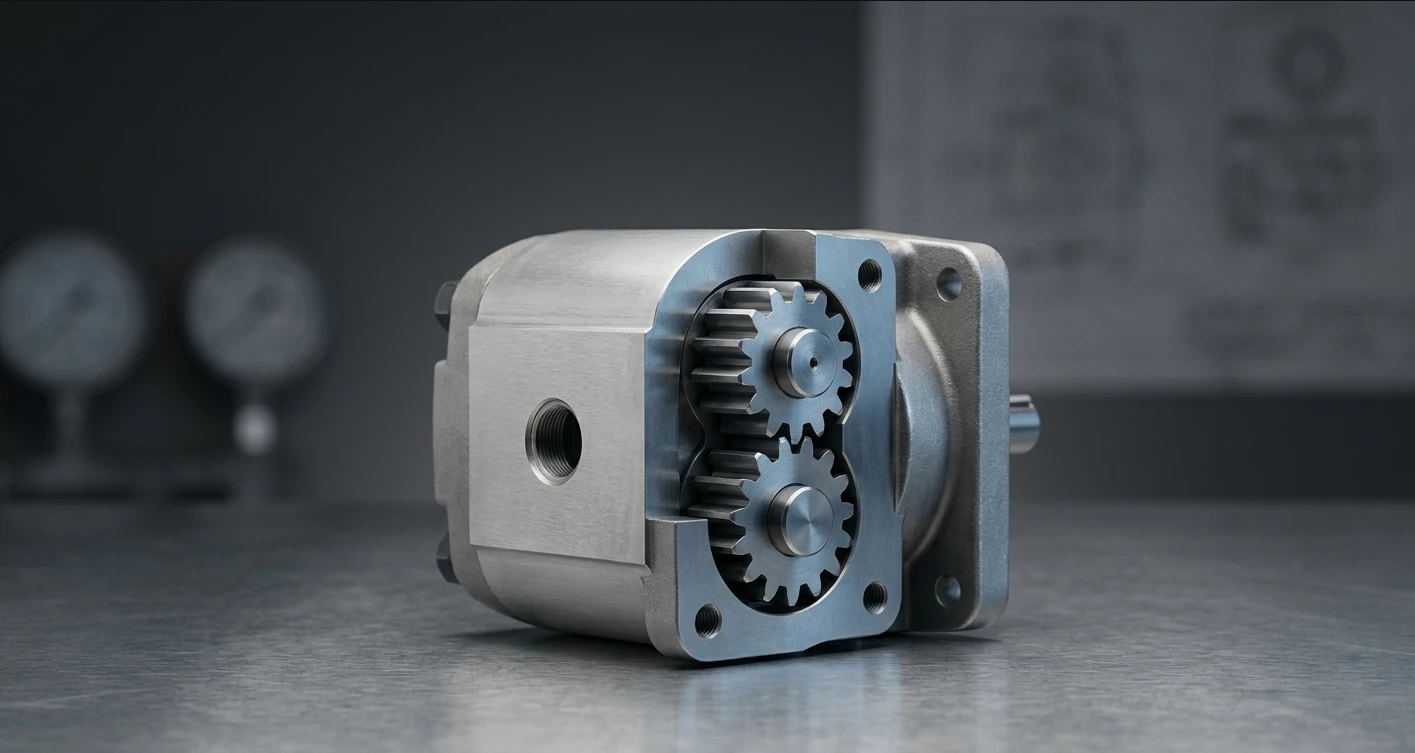
A hydraulic gear pump is a positive displacement pump that uses meshing gears to move hydraulic fluid at a near-constant volume per shaft revolution. Simple mechanics. Predictable output. Very few moving parts — that's the whole story in one sentence.
Why Industry Pros Still Care
Even as servo-hydraulic and electrified systems reshape the market, gear pumps still ship in enormous volumes across agriculture, construction, machine tools, and fluid transfer. Industry surveys through 2026 consistently place them as the highest-unit-volume hydraulic pump category worldwide.
The reason is boring but decisive: nothing else delivers the same horsepower-per-dollar with the same tolerance for imperfect fluid. That's a hard combination to beat when procurement is squeezing margins and the field is squeezing uptime.
How a Hydraulic Gear Pump Works
The hydraulic gear pump working principle is honestly easier to explain with your hands than with equations. Here's the version you can hand to a new hire on day one.
The Suction–Transfer–Discharge Cycle
As the drive shaft spins, the gear teeth on the inlet side unmesh. That creates an expanding cavity — a partial vacuum — which pulls fluid in from the reservoir. So far, so intuitive.
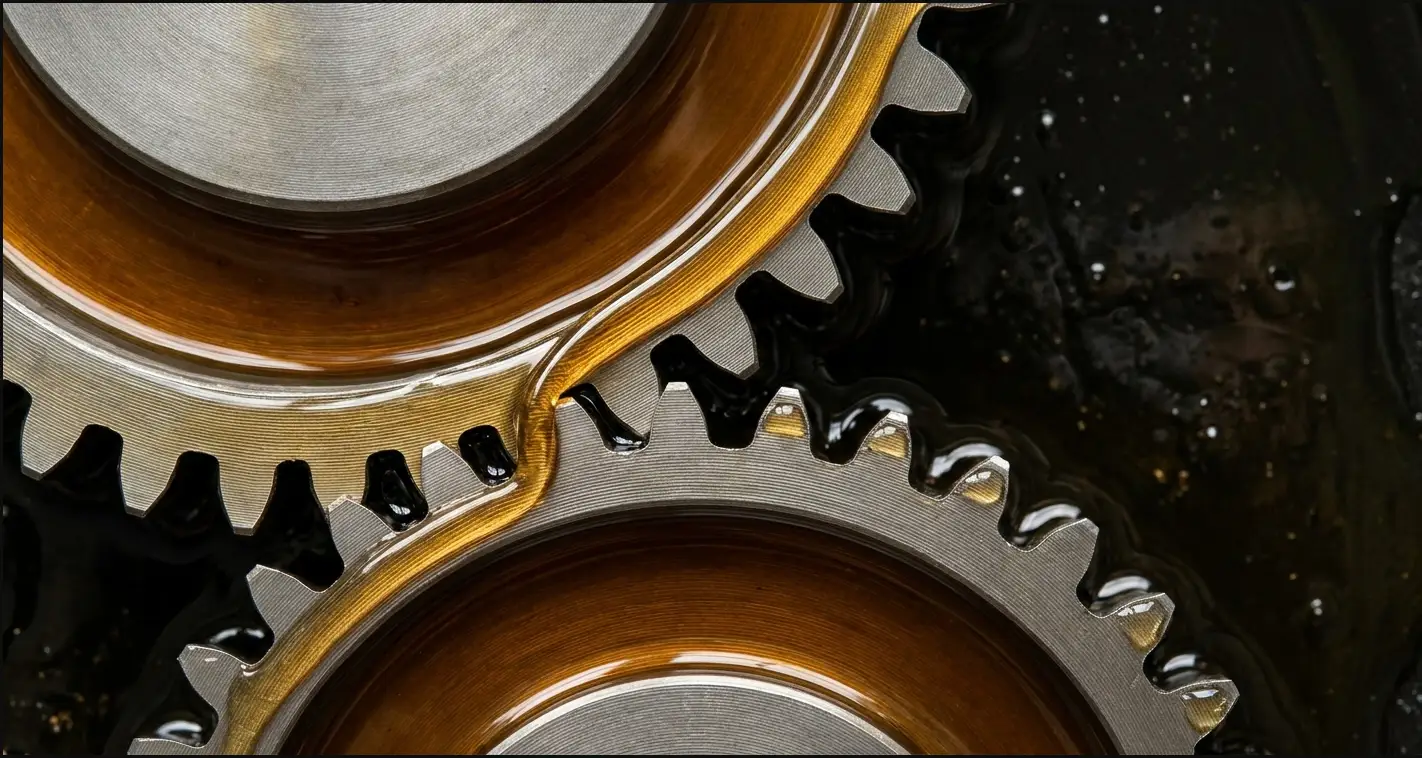
The fluid then rides in the pockets between the gear teeth and the housing wall, carried around the outside of each gear. It never crosses the mesh point in the middle.
On the outlet side, the teeth mesh back together. That collapses the pocket, forces the fluid out through the discharge port, and the cycle repeats — usually a few thousand times per minute.
Why It's Called a Positive Displacement Pump
Every revolution moves the same fixed volume of fluid, regardless of what's happening downstream. Load doubles? Flow stays the same — pressure just rises to match. That's the defining trait of any positive displacement pump, and it's why gear pumps behave so predictably in circuit design.
Pressure only builds when flow meets resistance. The pump doesn't "make" pressure — the system does. The pump just keeps moving fluid until the relief valve says otherwise.
Key Gear Pump Components and Operation
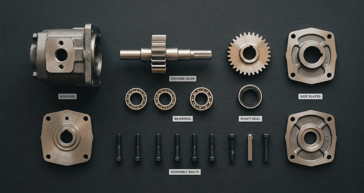
Six parts. Understanding them tells you exactly where a pump will fail first:
- Housing: the pressure boundary and the surface the gear tips seal against. Wear here shows up as internal leakage.
- Driving gear: connected to the input shaft; takes the mechanical load.
- Driven gear: idles on its own bearing, driven purely by mesh contact.
- Bearings or bushings: usually the first component to give up under contamination.
- Shaft seal: keeps fluid in and air out. Aeration usually starts here.
- Pressure-loaded side plates: ride against the gear faces and dynamically compensate for pressure, cutting internal leakage.
External vs. Internal Gear Pumps
Before you look at brands, budgets, or catalogs, get this classification right. The external gear pump vs internal gear pump decision drives roughly 80% of what happens next.
External Gear Pumps
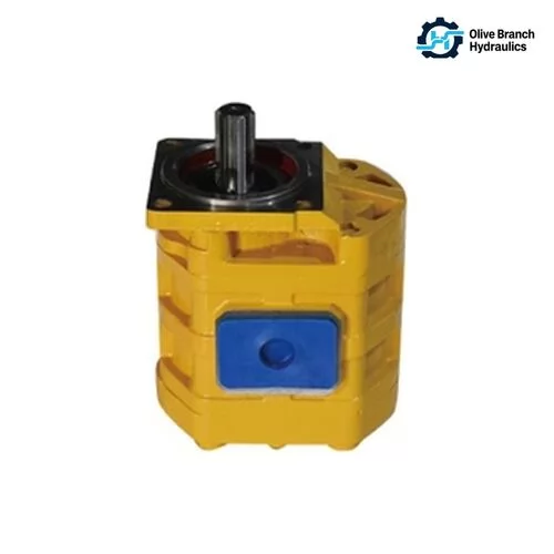
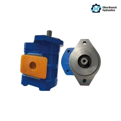
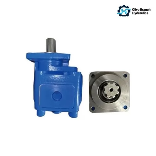
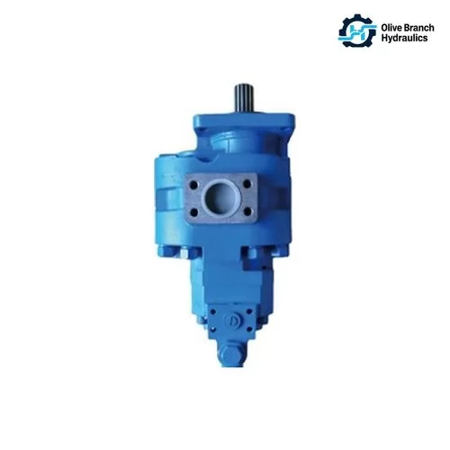
Two identical spur gears mesh side by side inside a figure-eight housing. This is the design most people picture when they hear "gear pump," and it dominates mobile hydraulics. Compact, cheap to manufacture, and handles high pressures well — but it's also the noisier of the two.
Internal Gear Pumps
Here a smaller gear (the pinion) rotates inside a larger ring gear, typically separated by a crescent-shaped seal. Flow is smoother, noise is lower, and viscosity tolerance is dramatically wider — which is why you'll find them on fuel oil, adhesives, and polymer duties where external designs would struggle.
Side-by-Side Comparison Table
| Feature | External Gear Pump | Internal Gear Pump |
|---|---|---|
| Typical Pressure | Up to 250–300 bar | Up to 200–250 bar |
| Speed Range | 500–3,500 rpm | 100–3,000 rpm |
| Noise Level | Higher (75–90 dB) | Lower (60–75 dB) |
| Viscosity Handling | 10–300 cSt | 1–100,000 cSt |
| Volumetric Efficiency | 85–92% | 88–95% |
| Typical Cost | Lower | Moderate to High |
| Best-Fit Applications | Mobile equipment, log splitters, loaders | Lubrication systems, fuel oil, polymers |
Performance Characteristics That Actually Matter on the Floor
Marketing sheets are full of numbers. These are the ones experienced specifiers actually check first.
Displacement, Flow, and Hydraulic Fluid Flow Rate
Displacement (cc/rev) multiplied by shaft speed (rpm) gives you theoretical flow. In real life, subtract 5–15% for internal leakage — and that leakage grows as pressure rises. Sizing off catalog flow at zero pressure is one of the most common rookie mistakes.
Pressure Ratings and Duty Cycles
Every gear pump datasheet lists three pressures: continuous, intermittent, and peak. Running continuously at the intermittent rating — never mind the peak — will slash service life from years to months. Match the rating to the actual duty cycle, not the worst case.
Efficiency Curves
Three efficiencies matter: volumetric (how much fluid actually makes it out), mechanical (how much shaft torque is lost to friction), and overall (the product of the two). A well-matched gear pump typically lands between 80–88% overall efficiency at its sweet spot — a number that erodes quickly outside its designed operating window.
Typical Performance Data Table
| Parameter | Small Frame | Medium Frame | Large Frame |
|---|---|---|---|
| Displacement | 1–8 cc/rev | 8–35 cc/rev | 35–100+ cc/rev |
| Max Pressure | 210 bar | 250 bar | 280 bar |
| Max Speed | 4,000 rpm | 3,000 rpm | 2,500 rpm |
| Typical Flow @ 1,800 rpm | 1.8–14 L/min | 14–63 L/min | 63–180 L/min |
| Overall Efficiency | 78–85% | 82–88% | 84–90% |
Where You'll Find Gear Pumps in the Field
Mobile & Off-Highway Equipment
Excavators, tractors, skid steers, backhoes, log splitters, and municipal vehicles. Anywhere the environment is rough, the fluid isn't always spotless, and rugged beats refined — gear pumps show up.
Industrial & Manufacturing Systems
Press feed circuits, machine tool lubrication headers, injection molding auxiliary drives, conveyor tensioners, and countless small power packs. Gear pumps are the quiet workhorse behind a lot of factory floors.
Fluid Transfer Duties
Fuel oil, lube oil, adhesives, chocolate, printing inks, and chemical dosing systems. Internal gear designs dominate here because they handle wildly varying viscosities without cavitating.
How to Choose the Right Hydraulic Gear Pump
Procurement wants the lowest price. Maintenance wants the longest life. Here's a checklist that satisfies both.
Match the Fluid First
Start with the fluid, not the pump. Mineral oil, water-glycol, biodegradable ester, or something more exotic — each one demands different seal compounds and housing metallurgy. Get this wrong and you'll be replacing the pump within weeks.
Size for Real Flow, Not Catalog Flow
Take theoretical flow, subtract volumetric losses at your actual operating pressure, then account for the lowest engine speed the machine will see in real duty. That's your true available flow — and it's often 15–25% below the glossy datasheet number.
Don't Ignore Mounting, Porting, and Shaft
SAE A/B/C flange vs. European four-bolt, keyed vs. splined shaft, side ports vs. rear ports — these details don't affect performance on paper, but a mismatch turns a two-hour install into a two-day rework.
Selection Checklist Table
| Decision Point | Key Question | Common Pitfall |
|---|---|---|
| Fluid Type | Mineral oil, water-glycol, biodegradable? | Wrong seal compound → premature leak |
| Operating Pressure | Continuous or peak? | Sizing to peak, running continuous |
| Flow Requirement | At what actual rpm? | Ignoring engine idle conditions |
| Contamination Level | ISO cleanliness code available? | Skipping filtration upgrades |
| Mounting Standard | SAE A/B, ISO, cartridge? | Adapter stack causing shaft misalignment |
Maintenance, Troubleshooting, and Service Life
Signs Your Gear Pump Is Failing
Rising case temperature, a cavitation whine that shifts pitch with load, pressure ripple showing up on the gauge, and external weeping at the shaft seal. Any one of these is a warning. Two together means schedule the swap now.
Root Causes Behind Most Failures
Contamination is still the number-one killer — nothing else even comes close. After that comes aeration (usually from a bad suction line), over-pressurization from a stuck or misadjusted relief valve, and shaft misalignment from a lazy install.
Expected Service Life Benchmarks
A well-installed gear pump on clean fluid at moderate duty typically delivers 5,000–15,000 operating hours before internal leakage forces a replacement. Push it hard on dirty oil and you can watch that number collapse to under 1,000 hours.
FAQ: Hydraulic Gear Pumps
Can a hydraulic gear pump run in reverse?
Most external gear pumps can be built bidirectional, but standard off-the-shelf designs are unidirectional because of shaft seal orientation and internal drain paths. Reversing a unidirectional pump usually pressurizes the shaft seal from the wrong side and blows it within minutes.
What's the difference between a gear pump and a gear motor?
The internals look nearly identical, but gear motors are engineered with different bearing loads, case drain provisions, and seals that can handle pressure on both ports. You can sometimes get away with running a pump as a low-duty motor, but it's not a design choice — it's a bandage.
Why is my new gear pump louder than the old one?
Nine times out of ten, it's aeration — a restricted suction strainer, a low reservoir level, or a loose inlet fitting drawing air. Fresh pumps get blamed constantly for what is actually a suction-side problem.
How does a gear pump compare to a piston or vane pump?
Gear pumps win on cost, simplicity, and tolerance for contamination. Piston pumps win on efficiency and offer variable displacement. Vane pumps sit in the middle — quieter than gears, cheaper than pistons, but pickier about fluid cleanliness than either.
What viscosity range do gear pumps handle best?
External gear pumps run happiest between 20–100 cSt at operating temperature. Internal gear pumps tolerate a much wider window — from thin fuel oils under 5 cSt up to heavy polymers well above 10,000 cSt.
Are hydraulic gear pumps still relevant with electrification trends?
Absolutely. On electrified mobile machines, the diesel engine gets replaced by an electric motor — but the hydraulic circuit downstream still needs a pump. Gear pumps remain the go-to for on-demand hydraulic functions because they're compact, cheap, and start-stop friendly.
Key Takeaways
- A hydraulic gear pump is a simple, rugged positive displacement device — flow tracks shaft speed, not system pressure.
- External designs dominate mobile hydraulics; internal designs win on smoothness, quiet operation, and viscosity range.
- Real-world flow always trails catalog flow — size for operating pressure, not benchtop conditions.
- Contamination is the top cause of premature failure. Clean fluid beats brand loyalty every time.
- Correct sizing, correct mounting, and correct fluid selection matter far more than the logo on the housing.