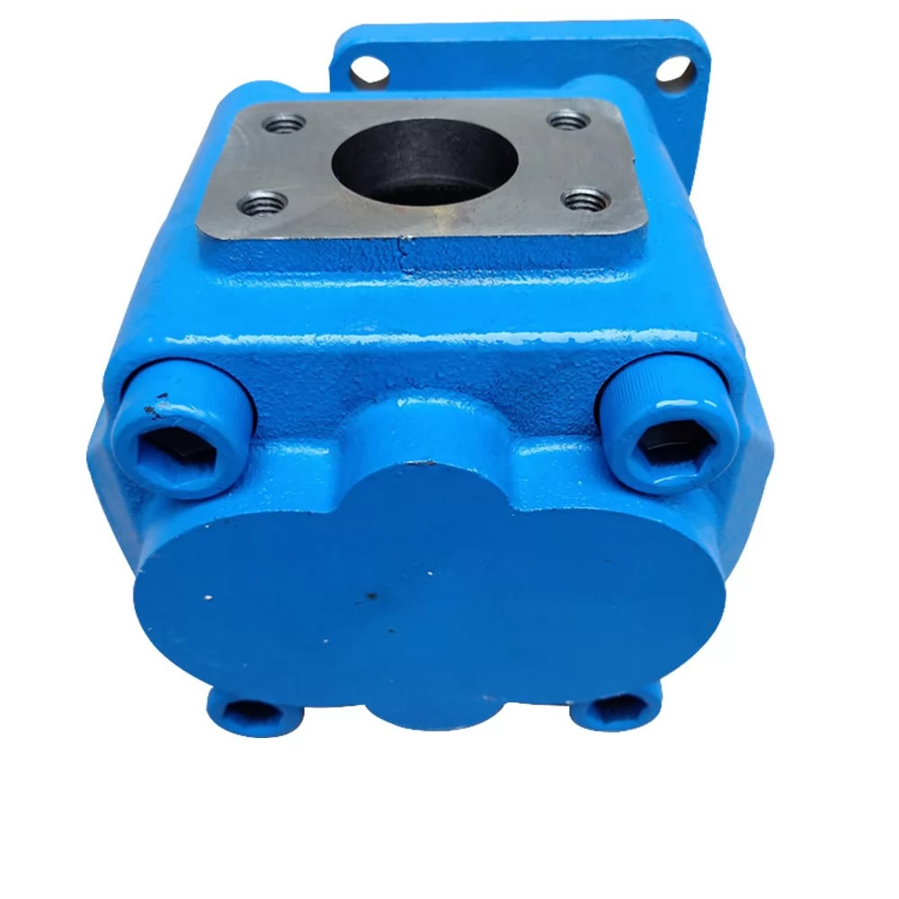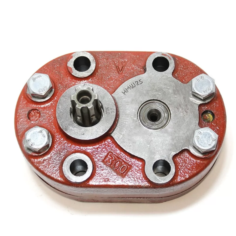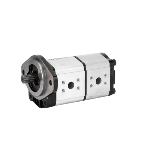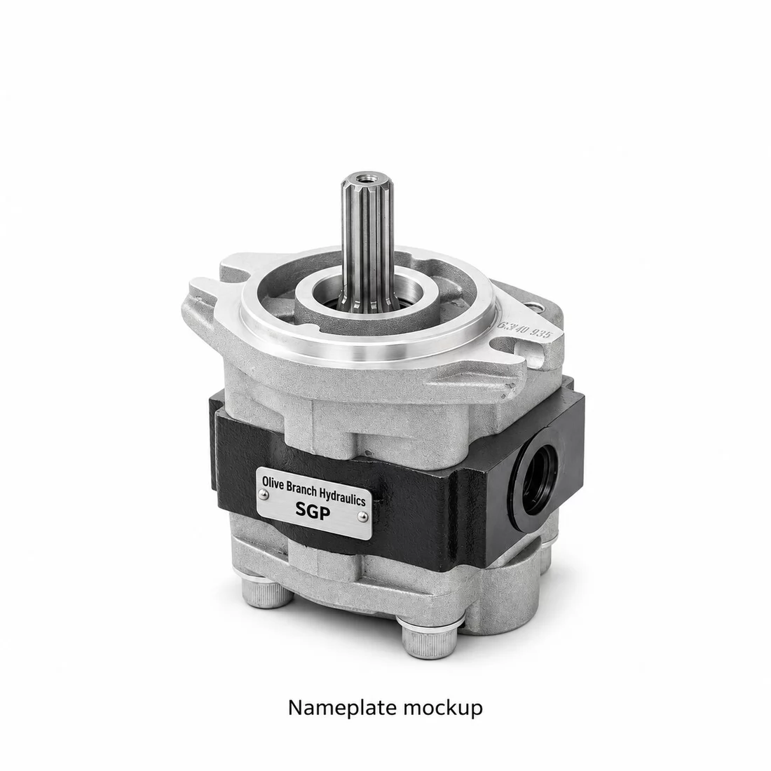

A replacement can bolt onto the flange and match the old displacement, then still fail within a season if the machine holds near-relief pressure for long stretches. So choosing a high pressure hydraulic gear pump starts with continuous pressure and duty cycle, followed by the mechanical interfaces. Displacement comes after both.
A high pressure gear pump is an external gear pump with a stiffer housing and heavier bearings. Its side plates are pressure-balanced, which lets it hold higher continuous ratings. It belongs on loaders, cranes, presses and tractors, where circuits sit near relief pressure for much of the cycle. Choose it on continuous pressure and duty cycle before you look at flow and fit.
What Makes a Gear Pump "High Pressure", and When Do You Actually Need One?
A gear pump earns the "high pressure" label by how long it can hold load, not only by how high that load goes. The housing is sized to survive sustained pressure without internal clearances opening up, and so are the side plates and bearings. You need one when the circuit spends much of its working cycle close to relief pressure. A circuit that only touches relief briefly does not need one.
An external gear pump is a positive-displacement pump in which two meshing gears carry oil around the inside of the housing from the inlet to the outlet. Pressure on the outlet side pushes both gears toward the inlet, and that load lands on the bearings. Every extra bar of pressure adds to it.
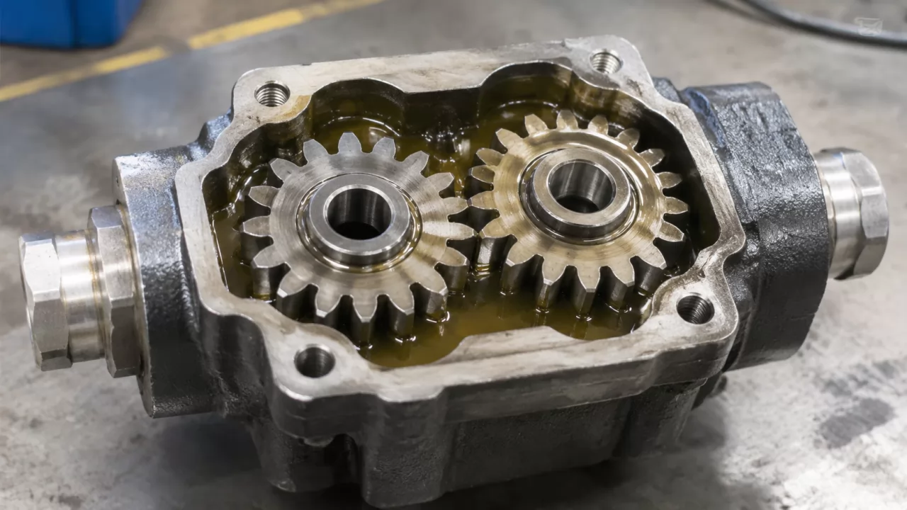
Leakage is the second problem. Oil slips across the gear faces and past the tooth tips, so as pressure climbs, volumetric efficiency falls and heat builds. High-pressure designs answer this with side plates, also called wear plates or thrust plates. Outlet pressure is fed behind them, so they press harder against the gear faces as load rises. A cast-iron body adds stiffness, keeping the bore from deflecting and opening up tip clearance.
When is the heavier construction worth paying for? Look at what the circuit does during a normal shift. A crane holding a load or a compactor pressing a bale keeps the pump loaded for seconds or minutes at a time. So does a dump body lifting near its limit, or a press dwelling at tonnage. Steering circuits and pilot supplies usually run well below relief, as do light auxiliary functions, and a lighter aluminum-body pump often handles that work at lower cost and weight.
Cast-iron high-pressure units are heavier and usually cost more. Some series also offer fewer interchangeable variants. Over-specifying adds expense and gains nothing, while under-specifying shows up later as worn side plates and scored bushings in a pump that runs hot and slow.
Gear Pump Displacement and Pressure Rating: Reading the Numbers That Matter
Every datasheet leads with displacement and pressure rating, and the two numbers answer different questions. Displacement sets flow at a given shaft speed. Service life is set by continuous pressure, not peak. Read the continuous rating first, then check that real pressure spikes stay inside the peak figure.
Displacement, Speed and Real Flow
Hydraulic gear pump displacement is the volume of oil moved per shaft revolution, given in cubic centimeters per revolution (cc/rev). To get theoretical flow in liters per minute, multiply displacement by speed in rpm and divide by 1,000. On paper, then, a 20 cc/rev pump at 1,500 rpm moves 30 L/min.
Delivered flow is lower, because internal leakage grows with pressure and temperature. You multiply by volumetric efficiency, which for a new gear pump commonly falls somewhere in the low-to-mid 90 percent range at rated conditions. At 92 percent the same pump delivers roughly 27.6 L/min, and less once the side plates wear. The nameplate tells you displacement, not the flow you will get at your pressure and oil temperature.
Continuous, Intermittent and Peak Pressure
Continuous pressure is the level the pump can hold indefinitely at rated speed, viscosity and temperature. Intermittent pressure sits higher and is allowed only for short periods; each manufacturer defines it, often as a time limit within a cycle. Peak pressure is the absolute ceiling for momentary spikes. Never treat it as a working level.
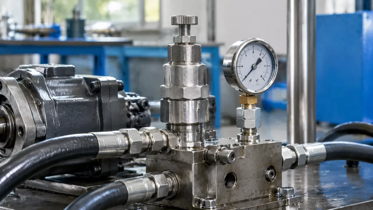
Spikes come from places a dial gauge rarely shows. A relief valve overshoots its setting as it cracks open. Stop a swinging boom hard, or let a cylinder bottom out, and a shock wave travels back to the pump outlet. A pressure transducer with fast logging on the actual machine will catch these events. If they exceed the peak rating, the pump is wrong for the job, even when the average pressure looks comfortable.
Key Specifications at a Glance
Confirm these parameters on every pump you quote or replace. The ranges are typical for common high-pressure gear pump series and are only meant for orientation; the manufacturer's datasheet for the exact code takes precedence.
| Parameter | Typical range or options | Check against |
|---|---|---|
| Displacement (cc/rev) | Single digits to about 100+ | Required flow at working speed |
| Continuous pressure (bar) | Typically about 200–280 for high-pressure designs | Logged working pressure plus margin |
| Peak pressure (bar) | Usually somewhat above continuous rating | Relief overshoot and shock spikes |
| Speed range (rpm) | Roughly 500 to 3,000, size dependent | Prime mover idle and maximum speed |
| Rotation | Clockwise or counterclockwise, viewed at shaft | Drive direction on the machine |
| Mounting flange | SAE two-bolt or European four-bolt | Existing gearbox or PTO pad |
| Shaft type | 1:8 taper, parallel keyed, SAE spline | Coupling or drive gear |
| Port type and position | Flange or threaded; side or rear | Hose routing and fittings |
| Operating viscosity (cSt) | Roughly 10–100, higher at cold start | Oil grade and ambient temperature |
Short on time before ordering? Verify continuous pressure, flange and shaft. Those three rows decide whether the pump survives and whether it fits at all.
How to Choose a High Pressure Gear Pump for a Specific Machine
Start from the machine's duty cycle and pressure profile, then confirm flow, and only after that the mechanical interfaces. Pressure and duty decide service life and flow decides performance; the interfaces decide whether the unit installs. Reverse that order and you end up with pumps that look right and still fail.
Pressure Profile and Duty Cycle
Find out how long the circuit holds pressure in each cycle and how many cycles run per hour. Then ask how many hours a day the machine works. A pump that sees full relief pressure for two seconds every minute lives a very different life from one that dwells there for thirty seconds, and logged data beats an operator's estimate. Margin comes next. Headroom below the continuous rating absorbs oil that runs hotter than planned and slight wear, along with the occasional overload. How much you leave depends on how steady the load is and what downtime costs you.
Drive, Speed and Inlet Conditions
Check the prime mover's full speed range, not just its rated speed. At low idle, some gear pumps lose too much flow to leakage at pressure. At high speed the inlet may not fill the gear pockets, and the result is cavitation: vapor bubbles forming and collapsing in the oil, pitting the gears and housing.
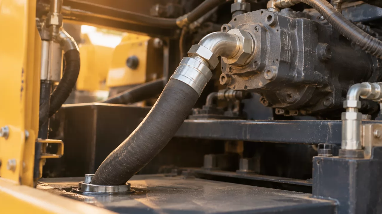
A pump that was rated correctly is often killed by its inlet. Suction lines are usually sized for low velocity, commonly cited as roughly 0.5 to 1.5 m/s. Avoid tight bends and partly clogged strainers, and don't ask the pump to lift oil a long way from a low reservoir. Cold oil at start-up is thick and starves the inlet, while hot oil thins out and raises leakage. Confirm the fluid temperature window against the pump's viscosity limits.
Mounting, Shaft and Port Interfaces
Mounting standards split broadly in two. SAE patterns, defined in SAE J744, use two-bolt A, B and C flanges with splined or keyed shafts; European four-bolt designs often use a 1:8 tapered shaft. Ports come as four-bolt flange ports to SAE J518 or ISO 6162, or as BSPP threads to ISO 228-1. SAE O-ring boss ports to SAE J1926 are the other common option.
Rotation direction is the easiest detail to get wrong. A pump built for clockwise rotation will not prime when driven counterclockwise, and many gear pumps can't be reversed without a rebuild. Port size and position decide whether existing hoses reach without new adapters.
As a working rule, keep normal pressure comfortably below the continuous rating and spikes inside the peak rating, and leave the interfaces until the pressure question is settled.
Which Body Material, Bearing Design and Pump Type Fits the Duty Cycle?
Let the duty cycle pick the body material and pump type. Aluminum-body gear pumps suit lighter, intermittent duty, while cast-iron pressure-balanced gear pumps are built for sustained high pressure. If the job needs variable flow or very high continuous pressure, a piston pump fits better, though it costs more and demands tighter filtration.
Many gear pumps run their shafts in plain bushings lubricated by the pumped oil. These are compact and tolerate some dirt, but only while viscosity holds up. Some heavy-duty designs switch to needle or roller bearings to carry higher radial load at sustained pressure.
Comparison: Gear Pump Constructions and Alternatives
Typical behavior by construction is set out below. Individual series vary, so read the pressure figures as hedged ranges.
| Criterion | Aluminum-body gear pump | Cast-iron high-pressure gear pump | Vane pump | Piston pump |
|---|---|---|---|---|
| Continuous pressure (typical) | Up to about 250 bar | Up to about 280–300 bar | Up to about 250–280 bar | Often 350 bar or more |
| Noise | Moderate to high | Moderate | Low | Moderate |
| Contamination tolerance | High | High | Moderate | Lower |
| Efficiency at pressure | Moderate, drops with wear | Moderate to good | Moderate to good | Highest |
| Life at sustained pressure | Limited | Good | Good within rating | Very good |
| Relative cost | Lowest | Low to moderate | Moderate | Highest |
In fixed-flow circuits that hold high pressure in dirty mobile conditions, the cast-iron gear pump is usually the sensible middle ground. Piston pumps make sense once efficiency or variable flow justifies the price.
Multi-Section and Tandem Configurations
Tandem, triple and quadruple gear pumps stack two or more pumping sections on one drive shaft. Each section can feed its own circuit from a single PTO or engine pad, say steering and implement circuits plus a cooling fan, which saves space and drive hardware.
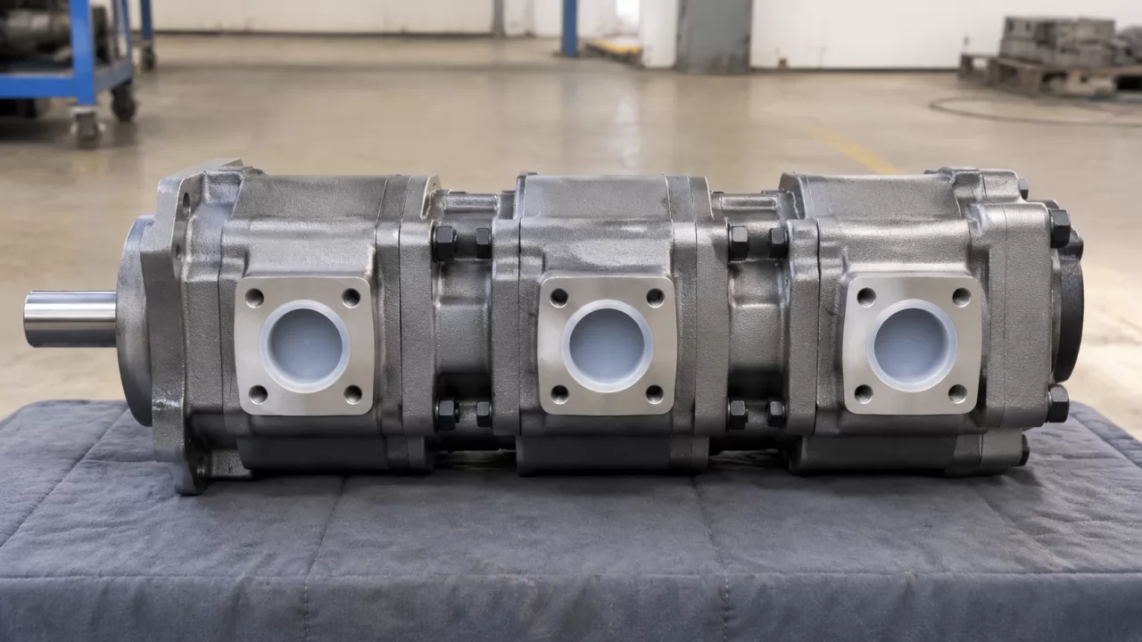
Torque is the catch. The first section's input shaft carries the combined torque of every section behind it. Input torque in Nm is roughly displacement in cc/rev multiplied by pressure in bar, divided by 20π and by mechanical efficiency. When two sections hit high pressure at the same moment, the sum can exceed what the shaft or coupling allows. Manufacturers publish maximum through-drive torque; check it against the worst simultaneous case rather than the average.
Matching Replacements and Specifying a Custom High Pressure Hydraulic Gear Pump
Match a replacement gear pump on the complete assembly code, not just the series name. A single series spans many displacements and rotations, along with several flange, shaft and port options. Custom units carry a different risk, which is dimensions drifting between quotation and sample. Lock the approval drawing before sampling starts and most of that risk goes away.
What to Send With an RFQ
A complete request saves a round of questions and gets you a firm quote instead of a provisional one.
- Send the original product code exactly as stamped on the nameplate.
- Name the machine model and add equipment details or serial range.
- State displacement plus continuous and peak pressure requirements.
- Specify rotation as viewed from the shaft end.
- Describe flange, shaft and port type, size and position.
- Give order quantity and destination port.
- Attach nameplate photos and existing drawings where you have them.
Leave any one of these out and pricing usually waits on a clarification email.
When the Code Alone Isn't Enough
A worn or painted-over nameplate can break the link between a code and the pump actually on the machine. Field modifications and regional variants do the same. Measuring the installed unit is the safeguard.
Note: Brand names and series numbers identify a pump family only. Compatibility depends on the full assembly code and on the interface dimensions you measure: pilot diameter, bolt spacing, shaft spline or taper, and port threads.
Custom Ports and Approval Drawings
Distributors stocking for several machine brands often want one body with different port configurations. Olive Branch Hydraulics handles this by configuring custom P/T ports and sending design drafts and 3D renders for approval before sampling, with replacement matching based on the original code and machine details. Check those drawings against your own measurements, not the catalog.
Where Gear Pump Selection Goes Wrong, and How to Check Before You Order
Most bad selections trace back to one of three mistakes: sizing on peak instead of continuous pressure, ignoring inlet conditions, or leaving inspection terms undefined until the goods arrive. Each is avoidable. Agree the pressure data and inlet layout in the quotation, together with the inspection checks, rather than assuming them.
No selection guide replaces a pressure trace from the actual machine. Where logging is impractical, the relief setting and the operator's account of dwell time are the next most useful evidence.
External Gear Pumps for Mobile Hydraulics: Vibration, Heat and Contamination
An external gear pump for mobile hydraulics works harder than the same pump in a stationary power unit. Engine vibration loads the bearings and mounting bolts. Cold starts send thick oil to the inlet, while summer work in a compact engine bay pushes oil temperature up and viscosity down. Dust gets in through cylinder rod seals and breathers.
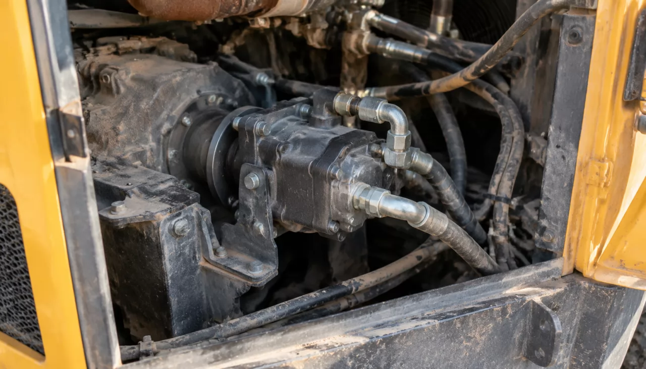
Gear pumps tolerate contamination better than piston pumps, but sustained high pressure narrows that margin. Many manufacturers specify cleanliness around ISO 4406 20/18/15 or cleaner for gear pumps. Shaft seals see pressure pulses and heat too, so check the seal material against oil temperature and fluid type.
Inspection and Documentation to Agree Up Front
Inspection terms written into the quotation can be enforced. Terms raised after shipment usually can't.
Tip: At the quote stage, agree which dimensional checks and leak inspection apply to your order, and whether pressure or flow tests are included. List the documents you need with the shipment. Third-party certificates belong to their holders, so ask what each document actually covers.
Frequently Asked Questions
Can a standard gear pump be run at high pressure if it's only for short bursts?
Yes, within its intermittent and peak ratings and only for the durations the manufacturer allows. Go beyond those limits repeatedly and bearing and side-plate life shortens, even if the pump seems fine at first.
How do I convert displacement into flow for my machine?
Multiply displacement in cc/rev by shaft speed in rpm, then divide by 1,000 for theoretical L/min. To estimate delivered flow, multiply that by volumetric efficiency at your working pressure and temperature.
Is a gear pump or a piston pump better for sustained high pressure?
That depends on the circuit. For fixed-flow duty, gear pumps win on cost and contamination tolerance. Piston pumps come out ahead on efficiency and variable flow at high continuous pressure.
What details speed up a quote for a replacement gear pump?
The full model or assembly code and the quantity, plus destination port and machine details. Nameplate photos and measured interface dimensions answer most of the follow-up questions before they're asked.