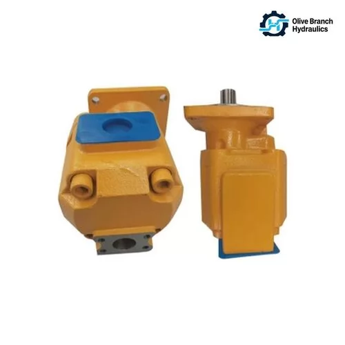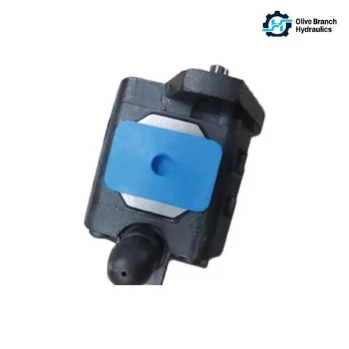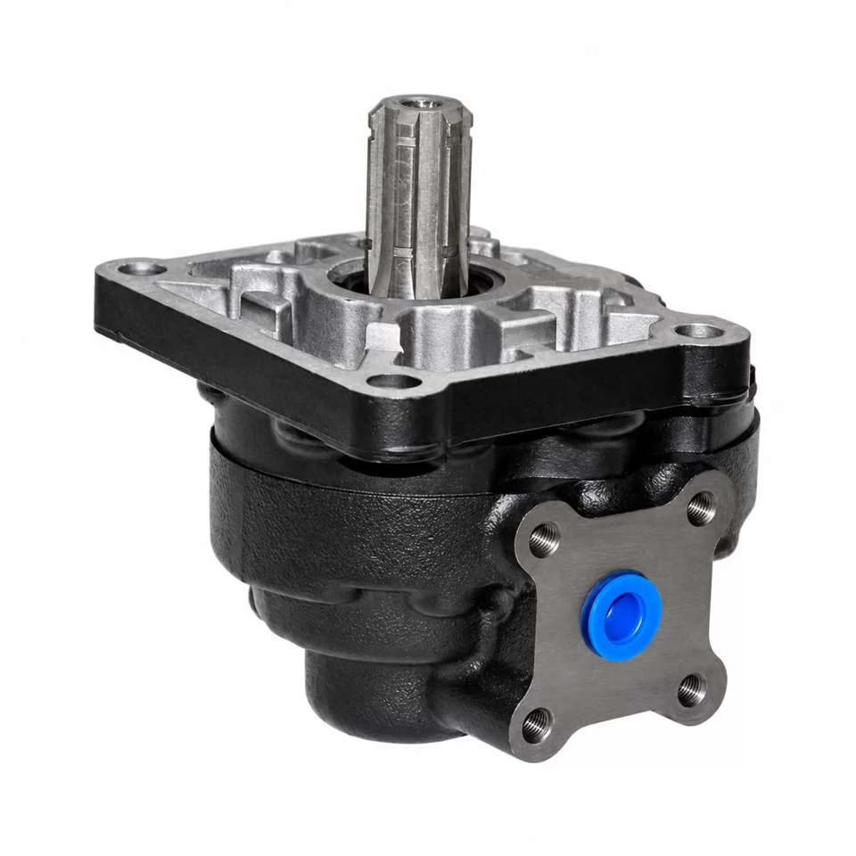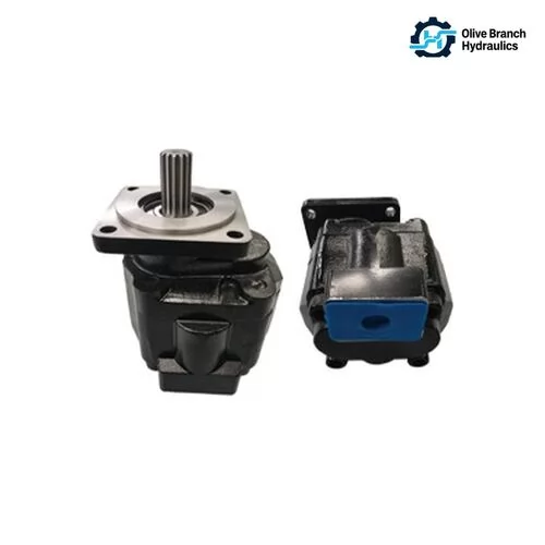

A replacement pump with a two-bolt flange where the gearbox expects four bolts won't go on the machine. Neither will a shaft with the wrong spline count. A pump with the wrong rotation goes on fine and then runs dry within seconds. Most gear oil pump failures in the field come back to one of these specification gaps, so this guide covers how to specify the unit, cross-reference it to the original and source it with fewer surprises.
What a Gear Oil Pump Does in a Hydraulic Circuit
A hydraulic gear pump is a fixed-displacement pump. It turns shaft rotation into a steady flow of oil by carrying fluid in the spaces between gear teeth and the housing. The pump does not create pressure on its own. Pressure builds only when that flow meets resistance from cylinders, motors and valves.
On the inlet side, the gears unmesh and open a cavity, and the oil fills it. The trapped oil then travels around the outside of each gear, against the housing wall, until the teeth mesh again at the outlet and force it out. Displacement is fixed by gear geometry, so each revolution moves the same volume. The only way to change the flow is to change the shaft speed.
Because the flow is fixed, the circuit needs a relief valve. Without one, a blocked line or a stalled actuator will push pressure up until something gives way.
External vs. Internal Gear Designs
An external gear pump uses two spur gears of the same size meshing side by side in a figure-eight housing. One is driven and the other is an idler. This is the compact, low-cost design found on most mobile machinery, tractors and power units. It tolerates some contamination, is simple to rebuild and comes in a very large number of displacements.
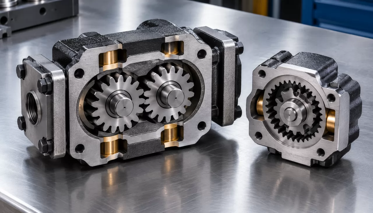
An internal gear pump runs a small external gear inside a larger ring gear with internal teeth, usually with a crescent-shaped spacer between them. A gerotor is a variant with no crescent, where an inner rotor with one tooth fewer turns inside an outer rotor. Both designs run quieter and pulse less. They tend to be used for narrower jobs such as quiet industrial power units, lubrication and charge circuits.
Where Gear Pumps Sit Next to Vane and Piston Pumps
Gear pumps are the right choice for fixed-flow duty at moderate pressure where cost, compactness and contamination tolerance count. Vane pumps, such as the T6/T7 or PV2R families, run quieter and suit industrial machines that need steady flow at medium pressure. Variable piston pumps, including the A10VO and A4VG families, are used where the circuit needs load-sensing, pressure compensation or very high continuous pressure. They cost more and need cleaner oil.
Which Hydraulic Gear Pump Type Fits Your Application?
Choosing a hydraulic gear pump type comes down to three questions. How many independent circuits does the machine run? What working pressure does each one need? How is the pump driven (engine, electric motor, gearbox or PTO)? Once those are answered, you'll usually have one or two candidate configurations before you look at displacement.
Single External Gear Pumps
A single-section external gear pump feeds one circuit and is the default for most loader, tipper, lift and small power-unit applications. Aluminum-body groups make up most of the replacement market. Common families include AZPF (Rexroth), ALP (Marzocchi), GHP (Marzocchi's higher-pressure range) and PGP505/PGP511/PGP517 (Parker). Within each family, the frame size sets the general dimensions and the gear width sets the displacement.
The 1PF2G series is a family of compact Rexroth-type gear pumps. It is often used where space is tight and flow demand is modest.
High Pressure, Tandem and Multiple-Section Pumps
A tandem gear pump joins two pumping sections on one through-drive shaft. Each section has its own outlet, so one engine pad can feed two separate circuits, for example steering and work hydraulics. Triple and quadruple units add more sections in the same way. Inlets may be shared or separate depending on the build.
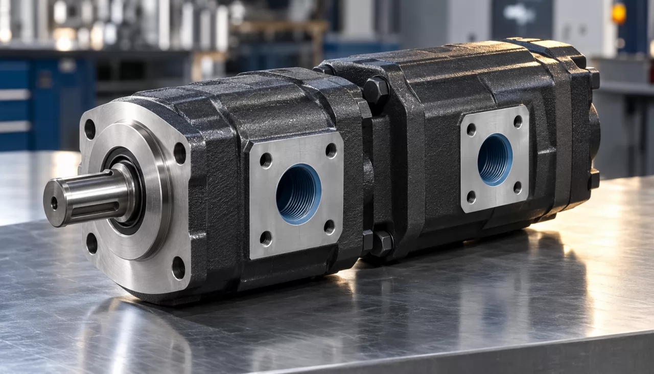
Each section can have a different displacement, so the full code describes every section. When you order a multiple-section unit, confirm the section order, the displacement of each section and the inlet layout. Swapping two sections changes which circuit gets which flow.
High pressure gear pumps use cast-iron bodies, heavier bushings and pressure-balanced side plates. They hold higher continuous pressure and tolerate the heat and shock loads seen on heavier construction machinery. Cast-iron families such as PGP315, PGP330 and PGP365 sit in this group. They are heavier and more expensive than aluminum units of similar displacement, so they are worth specifying only where the duty actually needs them.
Transmission and Tractor Hydraulic Pumps
Transmission pumps and tractor hydraulic pumps are designed around a particular gearbox housing or PTO interface. The flange pattern, pilot diameter, shaft length, spline and sometimes a drive gear or coupling are unique to that machine. For these units, matching the mounting and drive matters more than the catalog flow figure.
You'll usually need the tractor or transmission model and serial range, or the OEM part number. A displacement and flange type alone are rarely enough.
Reading Displacement, Pressure and Speed Ratings on a Gear Pump Datasheet
Gear pump displacement, given in cc/rev, times shaft speed in rpm, divided by 1,000, gives theoretical flow in L/min. A 16 cc/rev pump at 1,500 rpm therefore moves 24 L/min in theory. Pressure, speed and inlet limits then decide how much of that flow you actually get under real duty.
Displacement and Real Output Flow
Delivered flow is always below theoretical flow because oil leaks internally across the gear faces, tooth tips and bushings. That loss is called volumetric efficiency. A new external gear pump at rated conditions typically sits in the low-to-mid 90s percent, but the figure drops as pressure rises, oil thins out with heat and clearances open up with wear.
Size the pump with that in mind. If a circuit needs a set flow at working pressure and full operating temperature, a pump sized exactly to the theoretical figure will come up short. Check the flow curves at pressure on the datasheet, not just the nominal displacement.
Speed limits apply too. Datasheets give a minimum speed, below which internal leakage dominates and output becomes unreliable. They also give a maximum speed, above which the inlet can't fill the gear spaces and cavitation starts. Larger displacements in the same frame usually have lower maximum speeds.
Continuous, Intermittent and Peak Pressure
Most gear pump datasheets give three pressure ratings:
- Continuous pressure: the design figure the pump can hold for its rated life. Size the system's relief setting against this number.
- Intermittent pressure: a higher figure allowed for a limited share of each duty cycle, typically defined by the manufacturer as a maximum duration per event.
- Peak pressure: a short spike limit for valve shifts and shock loads. It is not a working point.
Ratings are often lower for the largest displacement in a frame, because wider gears put more load on the bushings. A family rated for high pressure overall may list a lower figure for its biggest sizes.
Fluid Viscosity, Temperature and Inlet Conditions
Gear pumps are specified for a working viscosity window and a maximum cold-start viscosity. Oil that is too thin when hot increases internal leakage and wear on the bushing faces. Oil that is too thick at start-up can't fill the gears and causes cavitation, a condition where vapor bubbles form at the inlet and collapse under pressure, eroding metal surfaces.
The inlet condition is usually given as a minimum absolute inlet pressure. A suction line that is too small, too long or has a clogged strainer pushes the inlet below that limit. The symptoms are a whining noise, foamy oil and pitting on the low-pressure side of the housing. Cleanliness matters as well. Datasheets often state a required oil cleanliness under ISO 4406, the standard that grades particle contamination by size and count.
How Do You Match a Replacement Gear Pump to the Original Model Code?
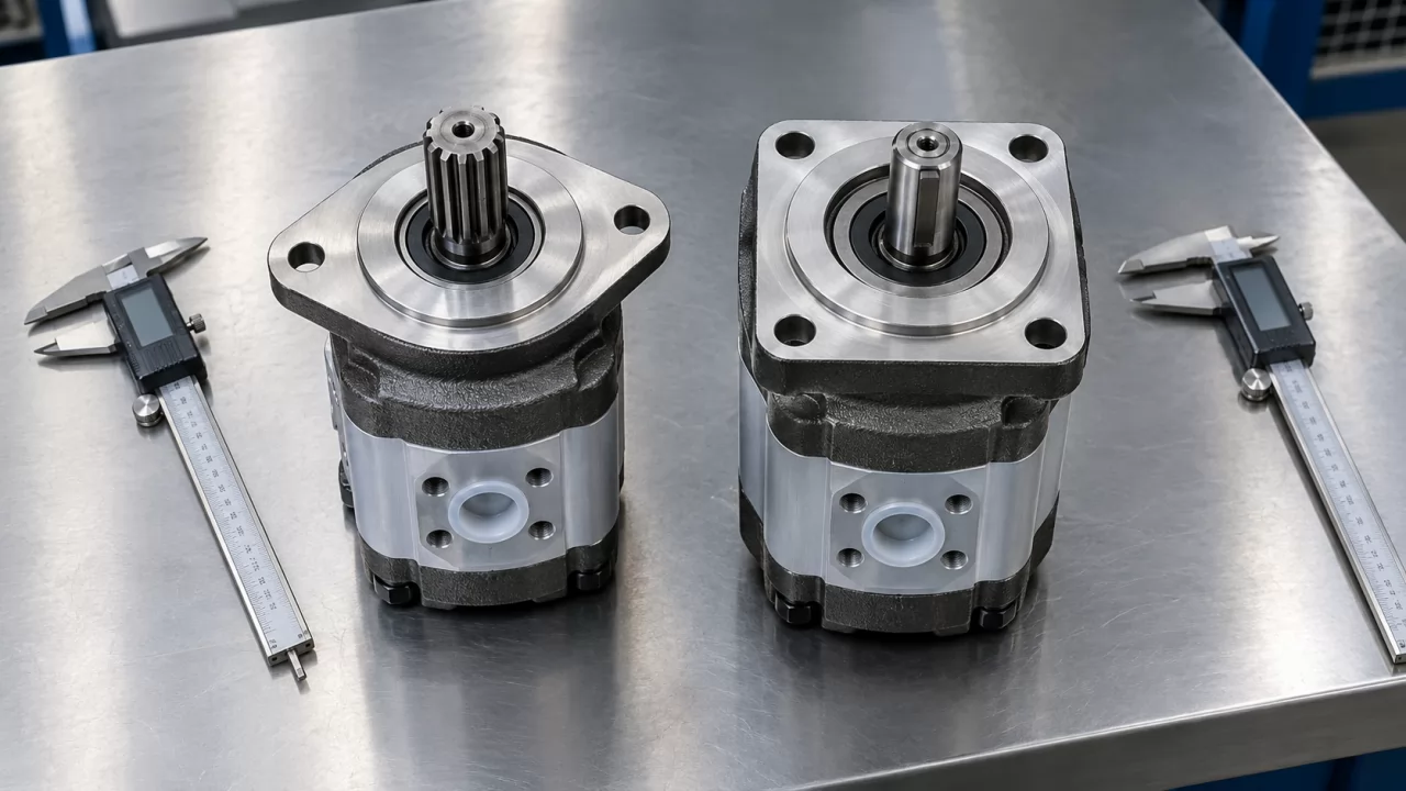
Matching a replacement gear pump starts with the complete assembly code on the original nameplate, not the series name. Two pumps from the same series can share displacement and still differ in flange, shaft, ports and rotation. Any one of those differences stops the unit fitting or working on the machine.
Series Names Are for Identification Only
References such as AZPF, PGP511 or GHP2 tell you the pump family and frame size. They don't tell you the build. A full code typically includes the displacement, rotation, flange type, shaft type, port style and position, seal material and any built-in valves. Brand names and model numbers are used only to identify the replacement. Compatibility depends on the complete assembly code, so an RFQ quoted on series name alone is incomplete.
Flange, Shaft, Ports and Rotation
These four details cause most fitment errors:
- Mounting flange: SAE two-bolt and four-bolt patterns, European four-bolt and various OEM-specific flanges differ in pilot diameter, bolt spacing and pilot depth. ISO 3019 covers many of the standard flange and shaft dimensions in both SAE and metric series.
- Shaft: splined (SAE or DIN, with a set tooth count and pitch), tapered with a key and nut, or parallel keyed. Shaft length and spline engagement have to match the drive coupling.
- Ports: split-flange, BSPP threaded, metric or UNF O-ring boss ports, located either on the side or at the rear. Port size and position decide whether existing hoses connect without adapters.
- Rotation: clockwise or counterclockwise, normally viewed from the shaft end. Many gear pumps are built for a single direction because of their bushing and seal layout, and running them backwards can starve the inlet or blow the shaft seal.
On multiple-section pumps, also check the shaft coupling between sections and whether the rear section has its own inlet.
What to Send When the Nameplate Is Missing
Worn, painted-over or missing nameplates are common in the maintenance market. A supplier can still rebuild the specification if you send these:
- The original product code or OEM part number, even if partial.
- The machine make, model and serial range, plus where the pump sits (main hydraulics, steering, fan drive, transmission).
- Measured details: flange bolt spacing and pilot diameter, shaft diameter and spline count, port sizes and positions, overall length.
- Rotation direction and, if you know it, the working pressure and engine speed.
- Clear photos of the flange face, shaft end, both port sides and any cast markings on the housing.
Olive Branch Hydraulics matches replacement parts from the original product code, machine model and equipment details. Sending all three in the first inquiry saves a round of questions.
What Separates a Reliable Gear Pump Supplier on Build Quality and QC?
A reliable gear pump supplier can explain the body material, bushing design, seal compound and gear finish of the unit being quoted. They also state how each pump is tested before shipment. Two pumps with the same code and similar prices can differ a lot in service life, depending on those internal choices and the inspection behind them.
Materials and Machining Points to Ask About
Ask about these points before you approve a sample:
- Body material: extruded or cast aluminum bodies keep weight and cost down for moderate pressure. Cast-iron bodies hold their shape better under high pressure and heat, which is why heavy-duty and high pressure families use them.
- Bushings and side plates: pressure-balanced bushings push against the gear faces in proportion to system pressure, which limits internal leakage as pressure rises. Ask what bearing surface or coating is used.
- Gears: case-hardened steel gears with ground tooth flanks and lapped faces keep tight clearances for longer. Gear face flatness and parallelism directly affect volumetric efficiency.
- Seals: NBR (nitrile rubber) suits standard mineral oils within normal temperatures. FKM (fluoroelastomer) handles higher temperatures and some fire-resistant or synthetic fluids. Confirm the compound against your fluid and the highest oil temperature you expect.
Machining accuracy on the housing bore, and the alignment between bore and pilot, also affects noise and bushing wear. Rebuilding an existing assembly cannot fix those problems.
Inspection and Documents to Agree in the Quotation
Put the inspection scope in writing before the order is confirmed. Typical items are dimensional checks against the drawing or original sample, leak inspection at the shaft seal and joint faces, and pressure and flow testing where applicable. ISO 4409 describes general methods for measuring the steady-state performance of positive-displacement pumps and is a reasonable reference if you want a test basis named.
List the documents you need as well, such as test records, a material declaration, a packing list or a certificate of origin. If a supplier refers to a third-party document, check whose name is on it. Those documents belong to their holders and are not the supplier's own certifications.
Olive Branch Hydraulics carries out a 100% final inspection before packaging. Its quality checks and required documents are agreed in the quotation, so the test scope can be set for each order.
What Drives Price, MOQ and Lead Time on Gear Pump Orders?
Price, MOQ and lead time on gear pump orders depend mainly on how standard the configuration is. A common displacement with a standard flange, shaft and ports moves fastest and costs least. Custom port layouts, multiple-section builds and extra sampling rounds add tooling, setup and approval time.
Cast-iron bodies cost more than aluminum. Each extra section on a tandem or triple pump adds gear sets, bushings and machining. Special shafts, integrated relief or priority valves, and non-standard seal compounds all add cost. Order quantity matters most on custom builds, where setup cost is spread over the batch. On standard codes, the effect is smaller.
When you send an RFQ, include the full model code, the quantity and the destination port. Olive Branch Hydraulics replies to quote requests within 24 hours when given those three details. Ask whether the quote is FOB or CIF, and make sure the agreed test scope is reflected in the price.
Custom Configurations and the Sampling Route
Custom hydraulic gear pumps, for OEM programs or aftermarket replacement, follow a set route. Olive Branch Hydraulics, for example, runs this sequence:
- Inquiry with model, application and target specification.
- Design drafts and 3D renders sent for your approval.
- Sampling against the approved design.
- Production with in-process quality control.
- 100% final inspection.
- Packaging and global shipping.
Custom P/T port configurations, meaning the position, size and thread of the pressure and tank ports, are a common request from distributors who want one housing to fit several machine layouts. Approve the render carefully. Port orientation errors show up only after the hoses are cut.
Common Sourcing Mistakes to Avoid
- Quoting on series name alone: the supplier fills the gaps with default options, and the shipped pump differs from the original in shaft, flange or rotation.
- Skipping a confirmed sample: going straight to bulk on a new code or new supplier removes the one chance to check fitment on the actual machine.
- Leaving test criteria out of the contract: with no agreed dimensional, leak and pressure/flow checks, you have no clear basis for rejecting a nonconforming batch.
Each of these can leave you with a whole batch of pumps that don't fit and are hard to return. The fix is the same in every case: put the full assembly code, the approved sample and the test scope in writing before production starts.