

If you've ever dealt with a hydraulic system that just won't cooperate — sluggish actuators, random pressure spikes, or parts wearing out way too fast — there's a good chance the piston pump pressure is off. It's one of those things that's easy to overlook, but getting the hydraulic pump pressure setting wrong can quietly drain energy, chew through components, and rack up serious downtime costs before anyone catches on.
This technical reference provides a systematic methodology for the precise calibration of piston pump pressure parameters. It encompasses procedural protocols for the safe adjustment of pump pressure relief valves, diagnostic frameworks for identifying and resolving prevalent system anomalies, and established best practices for maintaining consistent hydraulic system pressure regulation throughout all operational duty cycles.
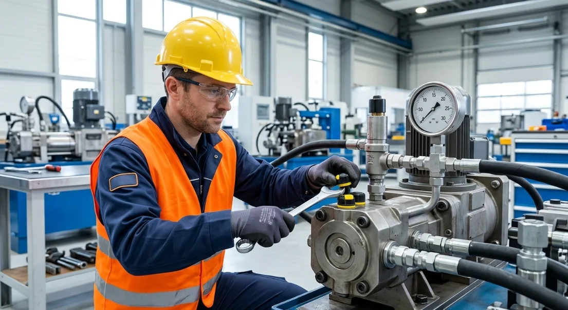
Understanding Piston Pump Pressure Fundamentals
How Piston Pump Pressure Regulation Works
Piston pump pressure is not generated by the pump itself — it's the result of resistance to flow within the hydraulic circuit. The pump delivers a fixed or variable volume of fluid, and system pressure builds as that fluid encounters load resistance from actuators, motors, or valves.
The relationship is straightforward: as load increases, pressure rises until it reaches the limit set by the pump pressure relief valve or pressure compensator. These components act as the ceiling, preventing the system from exceeding safe operating thresholds.
Displacement also plays a role in piston pump pressure adjustment. In variable displacement pumps, the swashplate angle decreases as pressure approaches the compensator setting, reducing flow output and stabilizing pressure without wasting energy as heat.
Types of Piston Pumps and Their Pressure Controls
Axial piston pumps position their pistons parallel to the drive shaft. Pressure control is typically achieved through a swashplate-mounted compensator that adjusts displacement angle in response to system pressure feedback.
Radial piston pumps arrange pistons perpendicular to the shaft, often using a cam ring or eccentric mechanism. These pumps commonly operate at higher pressures and rely on pilot-operated relief valves for pressure regulation.
The distinction between variable and fixed displacement is critical for pressure adjustment. Variable displacement pumps allow on-the-fly piston pump pressure adjustment through their built-in compensator. Fixed displacement pumps require an external system relief valve to control maximum pressure, since the pump always delivers full flow regardless of load.
Key Components Involved in Hydraulic Pump Pressure Setting
Understanding each component's role is essential before attempting any piston pump pressure adjustment. The table below maps the primary elements involved in hydraulic system pressure regulation.
| Component | Function | Role in Pressure Adjustment |
|---|---|---|
| Pressure compensator | Limits max system pressure | Primary adjustment point for variable pumps |
| Relief valve | Protects against overpressure | Sets the safety ceiling above compensator setting |
| Swashplate/cam ring | Controls displacement volume | Indirect pressure influence through flow reduction |
| Load-sensing valve | Matches output to demand | Fine-tunes operating pressure based on real-time load |
| Pilot valve | Signals compensator | Modulates response speed and sensitivity |
The pressure compensator and relief valve work in tandem. The compensator manages normal operating pressure, while the relief valve acts as the last line of defense. Always set the relief valve 200–500 PSI above the compensator setting to prevent simultaneous activation.
Tools and Preparation Before Adjusting Pressure
Required Tools and Equipment
Accurate piston pump pressure adjustment demands the right instruments. Using uncalibrated gauges or improper tools risks damaging adjustment screws and producing unreliable readings.
| Tool | Purpose |
|---|---|
| Calibrated pressure gauge (0.5% accuracy or better) | Accurate pressure reading at test port |
| Hex/Allen key set (metric and imperial) | Compensator screw adjustment |
| Locknut wrench (open-end or crow-foot) | Securing adjustment after setting |
| Infrared thermometer | Monitoring fluid temperature during adjustment |
| System schematic (OEM documentation) | Reference for port locations and specifications |
| Clean rags and plug caps | Preventing contamination at open ports |
Safety Precautions for Hydraulic System Pressure Regulation
Hydraulic systems store dangerous energy even when the pump is off. Trapped pressure in accumulators, cylinders, and hose assemblies can cause serious injury if released unexpectedly during piston pump troubleshooting.
Follow these mandatory safety steps before any adjustment:
- Lockout/tagout (LOTO): Isolate all energy sources including electrical, pneumatic, and mechanical. Tag the pump disconnect and verify zero energy state.
- Depressurize the system: Cycle actuators to release stored pressure. Open bleed valves and confirm gauge reads zero before loosening any fittings.
- Wear proper PPE: Safety glasses, hydraulic-rated gloves, and long sleeves. Hydraulic fluid under pressure can penetrate skin and cause severe tissue damage.
- Check fluid temperature: Hydraulic oil above 60°C (140°F) can cause burns. Allow the system to cool or wear heat-resistant gloves if adjustment must occur at operating temperature.
Never use your hand to check for leaks. A pinhole leak at 2,000 PSI creates an invisible jet that can inject fluid beneath the skin. Use cardboard or a leak detection solution instead.
Step-by-Step Piston Pump Pressure Adjustment Procedure
Step 1 — Identify the Current Pressure Setting
Connect a calibrated pressure gauge to the system test port nearest the pump outlet. This port is typically a minimess or JIC fitting identified in the OEM schematic as "P" or "HP."
Allow the system to reach normal operating temperature (usually 40–55°C / 104–131°F) before recording the baseline reading. Cold oil produces artificially high pressure readings due to increased viscosity, which will lead to incorrect piston pump pressure adjustment.
Document the current pressure, fluid temperature, and pump RPM. This baseline becomes your reference point for verifying the adjustment and for future piston pump troubleshooting.
Step 2 — Locate the Pressure Compensator or Relief Valve
Consult the OEM documentation to identify the exact location of the adjustment mechanism on your specific pump model. On most axial piston pumps, the pressure compensator is mounted directly on the pump housing, accessible via an external hex screw with a locknut.
For fixed displacement systems, the pump pressure relief valve is typically located on the valve manifold or inline between the pump and the directional control valves. Do not confuse the system relief valve with individual circuit relief valves — adjusting the wrong valve can create dangerous pressure imbalances.
Clean the area around the adjustment screw thoroughly before loosening anything. Contamination entering the compensator or relief valve during adjustment is a leading cause of subsequent pressure instability.
Step 3 — Adjust the Pressure Setting
Loosen the locknut while holding the adjustment screw stationary with the hex key. Turn the adjustment screw clockwise to increase pressure or counterclockwise to decrease pressure on most standard configurations.
Make adjustments in quarter-turn increments only. Each quarter turn typically changes pressure by 200–500 PSI depending on the pump model and spring rate. Rushing this step with large adjustments risks overshooting the target and stressing system components.
After each quarter turn, allow the system to stabilize for 10–15 seconds before reading the gauge. This pause lets the compensator spool fully respond and gives you an accurate representation of the new hydraulic pump pressure setting.
Step 4 — Verify and Lock the Setting
Once the gauge reads your target pressure, cycle the system under load at least three times. Confirm the pressure holds steady at the set point during each cycle and returns to standby pressure when the load is removed.
Tighten the locknut firmly while holding the adjustment screw in position with the hex key. Recheck the gauge after tightening — locknut torque can shift the screw slightly, changing the setting by 50–100 PSI.
If the pressure shifted during locknut tightening, loosen and readjust. This verification loop is essential for reliable hydraulic system pressure regulation.
Step 5 — Test Under Operating Conditions
Run the machine through its full duty cycle at normal operating speed and load. Monitor the pressure gauge continuously during the first several cycles, watching for spikes, drops, or oscillations that indicate instability.
Listen for abnormal noise — whining suggests cavitation, knocking indicates pressure spikes, and grinding points to mechanical wear. Inspect all fittings, hoses, and the pump housing for new leaks that may have developed at the higher or lower pressure setting.
Record the final verified pressure, date, and any observations in your maintenance log. This documentation supports future piston pump troubleshooting and establishes a performance baseline for the adjusted setting.
Piston Pump Pressure Adjustment Reference Table
Use this reference table to identify the typical pressure range and adjustment method for your specific pump type. Always verify against OEM specifications, as individual models may vary.
| Pump Type | Typical Pressure Range (PSI) | Adjustment Method | Common Valve Type |
|---|---|---|---|
| Axial piston (variable) | 3,000–6,000 | Compensator screw | Pressure compensator |
| Axial piston (fixed) | 2,500–5,000 | System relief valve | Direct-acting relief |
| Radial piston | 5,000–10,000 | Pilot-operated valve | Pilot relief valve |
| Bent-axis piston | 5,000–7,000 | Compensator + relief | Dual-stage valve |
Important: The relief valve should always be set 200–500 PSI above the compensator setting on variable displacement pumps. Setting them at the same value causes both to activate simultaneously, generating excessive heat and reducing pump life.
Piston Pump Troubleshooting — Common Pressure Problems
Pressure Too Low
Low pressure is the most common complaint during piston pump troubleshooting. The system feels weak, actuators move slowly, and the machine cannot perform its rated work.
| Symptom | Likely Cause | Solution |
|---|---|---|
| Sluggish actuators | Worn compensator spring | Replace spring to restore set point accuracy |
| Pressure won't build past a low threshold | Internal pump leakage (worn pistons/barrel) | Inspect piston seals and cylinder barrel for scoring |
| Erratic gauge reading | Air in system | Bleed air from high points and refill reservoir |
| Gradual pressure loss under load | External leakage at fittings or shaft seal | Tighten fittings or replace shaft seal |
| Pressure drops when oil heats up | Viscosity breakdown or wrong fluid grade | Replace fluid with OEM-specified grade |
Pressure Too High
Excessive pressure accelerates wear on every component in the circuit. It also wastes energy by converting excess hydraulic power into heat rather than useful work.
| Symptom | Likely Cause | Solution |
|---|---|---|
| Overheating fluid | Relief valve set too high | Reduce relief valve setting to specification |
| Hose or fitting failure | Blocked return line or filter | Clear obstruction and replace collapsed hoses |
| Pump noise and cavitation | Compensator stuck in closed position | Clean or replace compensator spool |
| Cylinder drift or seal blowout | Pressure spike from rapid valve closure | Install shock valves or adjust deceleration ramps |
Pressure Fluctuations and Instability
Unstable pressure — where the gauge needle oscillates or the system surges — indicates a dynamic problem rather than a simple mis-setting. This requires systematic piston pump troubleshooting to isolate the root cause.
Common causes of pressure fluctuation include:
- Contaminated hydraulic fluid: Particles lodging in the compensator spool or relief valve seat prevent clean sealing, causing intermittent pressure drops and spikes.
- Worn swashplate bearings: Excessive play allows the swashplate angle to shift under load, creating cyclical pressure variations synchronized with pump rotation.
- Faulty load-sensing valve: A sticking or worn load-sense element sends incorrect feedback signals, causing the compensator to hunt between high and low displacement.
- Air entrainment: Dissolved or entrained air compresses under pressure and expands during low-pressure phases, creating a spongy, oscillating pressure response.
Start diagnosis by checking fluid condition and filtration. Over 80% of hydraulic system failures trace back to contamination, making it the most productive first step in any piston pump troubleshooting process.
Maintenance Tips for Consistent Hydraulic System Pressure Regulation
Scheduled Inspection Intervals
Consistent hydraulic pump pressure settings require proactive maintenance rather than reactive repairs. Establish a schedule based on operating hours and environmental severity.
- Monthly: Check system pressure with a calibrated gauge and compare to baseline. Inspect for external leaks around the compensator and relief valve.
- Quarterly: Replace return-line and pressure filters. Sample hydraulic fluid for particle count, water content, and viscosity.
- Annually: Service the pressure compensator — clean the spool, inspect the spring, and replace seals. Recalibrate or replace pressure gauges.
- Every 5,000 hours: Perform a full pump efficiency test. Compare actual flow and pressure output against OEM specifications to detect internal wear.
Fluid Quality and Its Impact on Pressure Stability
Hydraulic fluid is not just a power transmission medium — it's a precision control element. Degraded fluid directly undermines your piston pump pressure adjustment by altering the behavior of compensators, relief valves, and pilot circuits.
Contamination causes spool stiction and valve seat erosion, leading to erratic pressure control. Maintain fluid cleanliness to ISO 18/16/13 or better for piston pump systems. Use 10-micron absolute filtration on both pressure and return lines.
Viscosity breakdown from overheating or oxidation increases internal leakage across piston-to-barrel clearances. This manifests as gradual pressure loss that worsens as the fluid heats up during operation. Monitor viscosity during quarterly fluid sampling and replace fluid when it falls outside the OEM-specified range.
Aeration — air mixed into the fluid — compresses under pressure and creates an unstable, spongy system response. Check reservoir level, inspect suction line fittings for air ingress, and verify shaft seal integrity to eliminate aeration sources.
Frequently Asked Questions (FAQ)
What happens if piston pump pressure is set too high?
Excessive pressure generates surplus heat as the relief valve continuously dumps flow back to tank. This accelerates seal degradation, shortens hose life, and increases the risk of catastrophic fitting failure. Energy consumption also rises significantly because the pump works harder than necessary, converting wasted hydraulic power into thermal energy that the cooling system must then dissipate. Over time, chronically high pressure can score cylinder walls and damage actuator seals throughout the circuit.
How often should I check my hydraulic pump pressure setting?
Under normal operating conditions, check system pressure monthly using a calibrated gauge and compare the reading to your documented baseline. In high-duty applications — such as continuous press operations, mobile equipment in harsh environments, or systems running more than 16 hours per day — increase the frequency to weekly checks. Any time you notice performance changes like slower cycle times or increased noise, verify pressure immediately as part of your piston pump troubleshooting routine.
Can I adjust pressure while the pump is running?
Yes, most pressure compensator adjustments are designed to be made with the pump running at normal operating temperature. In fact, adjusting under cold or static conditions produces inaccurate results. However, never adjust a system relief valve under full load without proper safety measures in place — a sudden pressure spike during adjustment can cause hose failure or component damage. Always ensure your body is positioned away from potential leak paths and that all personnel are clear of actuator movement zones during live adjustments.
What is the difference between the compensator and the relief valve?
The pressure compensator is the primary control device that regulates normal operating pressure by reducing pump displacement when the set pressure is reached. It operates continuously during normal system function and is designed for frequent cycling. The relief valve, by contrast, is a safety device that only opens when pressure exceeds a preset maximum — typically 200–500 PSI above the compensator setting. If your relief valve is opening during normal operation, it indicates the compensator has failed or is set incorrectly, and the system is wasting energy as heat.
Why does my piston pump lose pressure over time?
Gradual pressure loss typically stems from internal wear that increases leakage across close-tolerance components. The most common causes include worn piston rings or slippers that allow fluid to bypass from high-pressure to low-pressure chambers, degraded shaft seals that create external leakage, contaminated fluid that erodes valve seats and spool lands, and a fatigued compensator spring that can no longer maintain its calibrated force. Fluid degradation compounds the problem — as viscosity drops from overheating or oxidation, internal leakage rates increase further, creating a progressive decline in system pressure capability.
Do I need a technician for piston pump pressure adjustment?
Basic piston pump pressure adjustment — turning the compensator screw to match a documented specification — can be performed in-house by maintenance personnel who have proper training, calibrated tools, and access to OEM documentation. However, if the adjustment doesn't resolve the issue, or if you're dealing with complex symptoms like pressure oscillation, load-sensing calibration, or multi-pump synchronization, a certified hydraulic specialist brings diagnostic expertise and specialized test equipment that can identify root causes more efficiently. When in doubt, the cost of a service call is far less than the cost of a pump destroyed by incorrect adjustment.



