

Gear pump failures cost hydraulic systems thousands in downtime annually — yet most defects trace back to micron-level dimensional errors detectable only through three-coordinate measurement. Here's how CMM technology is transforming gear pump quality control and preventing costly breakdowns before they happen.
Anyone who's worked with hydraulic systems knows that gear pumps do the heavy lifting when it comes to fluid power. The tricky part is that even small errors in tooth geometry or bore alignment — things you can't spot with the naked eye — have a way of snowballing into serious problems down the line. That's where three-coordinate measurement comes in. It's really the most reliable way to catch those hidden defects before they ever leave the shop floor.
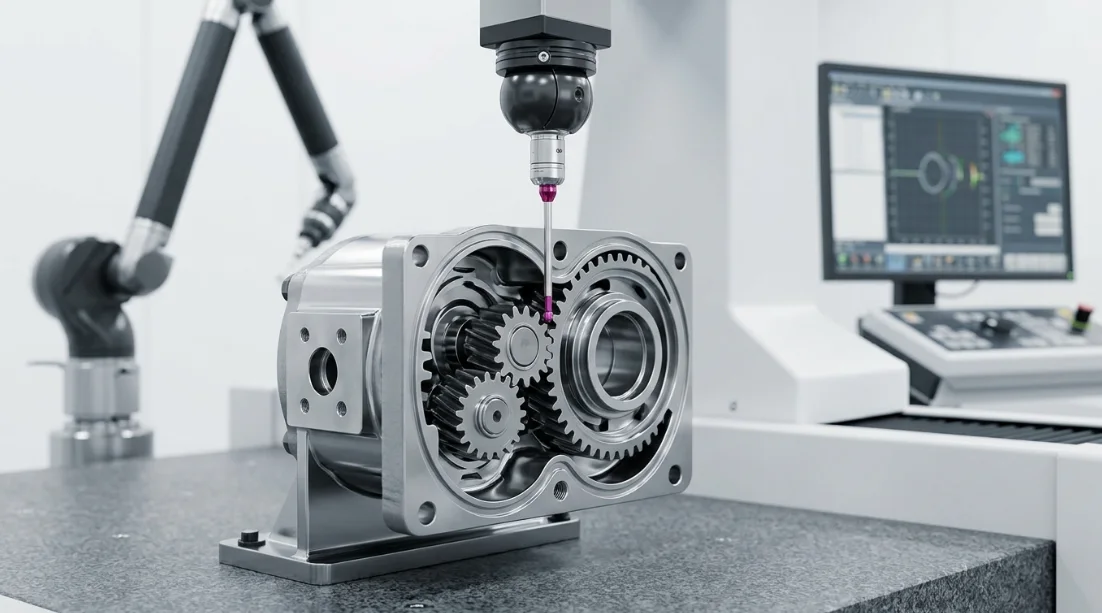
Understanding Three Coordinate Measurement for Gear Pumps
What Is a Coordinate Measuring Machine (CMM)?
A Coordinate Measuring Machine is a precision metrology instrument that captures the physical geometry of an object by probing discrete points or scanning surfaces in three-dimensional space. The machine operates along X, Y, and Z axes with nanometer-level encoder resolution, translating physical features into digital coordinate data.
For gear pump inspection methods, CMMs typically employ two probe technologies. Tactile touch-trigger probes capture individual point data with high repeatability, while analog scanning probes trace continuous surface profiles essential for involute gear tooth evaluation.
The working principle relies on establishing a coordinate reference frame aligned to the part's datum features. Once aligned, every measured point is expressed relative to this frame, enabling direct comparison against nominal CAD geometry and GD&T specifications.
Why Gear Pumps Demand Precision Dimensional Testing
Gear pumps operate on the principle of meshing gear teeth trapping and displacing fluid within tight-clearance housing cavities. This operating principle means that dimensional accuracy directly governs volumetric efficiency, pressure capability, and service life.
Tooth profile accuracy must be maintained within ±0.005 mm to ensure smooth meshing without excessive pulsation or noise. Pitch deviations beyond tolerance create uneven load distribution that accelerates wear on specific teeth.
Bore alignment and housing geometry are equally critical. A center distance error of just 0.01 mm between gear bores can increase internal leakage by 15–20%, dramatically reducing pump efficiency. These tolerances place gear pump dimensional accuracy squarely within the domain of coordinate measurement technology.
Hydraulic pump quality control standards from ISO, AGMA, and DIN all specify dimensional verification requirements that only CMM-class instruments can reliably satisfy.
Key Components of a Gear Pump Measured by CMM
Every functional surface of a gear pump contributes to its sealing integrity and flow characteristics. The following table summarizes the critical components, their key dimensions, and the tolerances that coordinate measuring machine gears inspection must verify.
| Component | Critical Dimension | Typical Tolerance |
|---|---|---|
| Gear teeth | Tooth profile & pitch | ±0.005 mm |
| Gear bore | Diameter & cylindricity | ±0.003 mm |
| Housing cavity | Flatness & parallelism | ±0.008 mm |
| Shaft journals | Concentricity & runout | ±0.004 mm |
| End plates | Surface flatness | ±0.006 mm |
These tolerances represent the boundary between a pump that delivers rated performance and one that suffers premature failure. CMM gear tooth measurement provides the only practical method for verifying all these features on a single platform.
Three Coordinate Testing Process for Gear Pumps
Pre-Measurement Preparation
Successful CMM inspection begins long before the probe contacts the part. Thermal stabilization is the first critical step — gear pump components must equilibrate to the measurement room temperature (typically 20°C ±1°C) for a minimum of four hours to eliminate thermal expansion errors.
Fixturing must secure the component rigidly without introducing clamping distortion. For gear bodies, V-block fixtures or expanding mandrels provide stable support while leaving critical surfaces accessible to the probe.
Datum selection follows the functional assembly hierarchy. The primary datum is typically the bore axis, secondary is an end face, and tertiary is established by a locating feature such as a dowel hole. This datum scheme mirrors how the component functions in the assembled pump.
Probe calibration uses a certified reference sphere to establish the effective probe tip radius and stylus vector. For coordinate measuring machine gears work, star-stylus configurations allow access to tooth flanks without probe changes, reducing measurement cycle time and eliminating probe-change uncertainty.
CMM Gear Tooth Measurement Methodology
CMM gear tooth measurement follows a systematic sequence designed to capture the full geometric character of the gear. The process begins with establishing the gear's rotational axis by measuring the bore or shaft diameter and extracting the cylinder axis.
Step 1: Axis and reference establishment. The CMM measures multiple cross-sections of the gear bore to define the rotational axis. A reference tooth is identified to establish the angular zero position.
Step 2: Involute profile scanning. The probe traces along the tooth flank from root to tip, capturing the actual involute curve. Continuous scanning mode collects hundreds of points per flank, providing detailed profile form data.
Step 3: Lead measurement. The probe traverses along the tooth face width at a constant roll angle, capturing helix deviation across the gear width. This reveals crowning, taper, or twist errors.
Step 4: Pitch deviation assessment. Point-to-point probing captures the angular position of each tooth at a reference diameter. Single pitch deviation and cumulative pitch deviation are calculated from these measurements.
Step 5: Tooth thickness verification. Chordal or span measurements across multiple teeth confirm material condition and backlash characteristics essential to gear pump dimensional accuracy.
Measuring Housing and Bore Geometry
The gear pump housing presents unique measurement challenges due to its internal cavity geometry. CMM inspection of the housing focuses on bore center distance, cavity form, and sealing surface flatness.
Bore center distance measurement uses a circle-fitting algorithm applied to multiple probed points within each gear bore. The distance between fitted circle centers must match the nominal value within ±0.005 mm to ensure proper mesh engagement.
Internal cavity dimensions are captured using long-reach styli that can access deep features without collision. The cavity profile must maintain consistent clearance around the gear tip circle to prevent interference while minimizing leakage paths.
Sealing surface flatness is evaluated by scanning a grid pattern across mating faces. Flatness errors exceeding 0.008 mm compromise the gasket seal and lead to external leakage under pressure.
Data Acquisition Parameters
The following table details the measurement parameters, methods, and governing standards applied during three-coordinate testing of gear pump components.
| Parameter | Method | Standard Reference |
|---|---|---|
| Involute profile | Continuous scanning | ISO 1328-1 |
| Tooth pitch deviation | Point-to-point probing | AGMA 2015 |
| Bore center distance | Circle fitting algorithm | ISO 286 |
| Surface flatness | Planar scan grid | ISO 12781 |
| Runout | Rotational axis measurement | ISO 1101 |
Scanning density and probe speed are balanced against measurement uncertainty requirements. Higher point density improves form characterization but increases cycle time. For production gear pump inspection methods, optimized scan paths capture critical features efficiently without sacrificing data quality.
Interpreting CMM Results for Gear Pump Quality
Common Deviations and Their Causes
Understanding the relationship between measured deviations and their manufacturing root causes is essential for effective hydraulic pump quality control. The following table maps common CMM findings to their likely origins and performance impacts.
| Deviation Type | Likely Cause | Impact on Pump Performance |
|---|---|---|
| Profile form error | Tool wear during hobbing | Increased noise & pulsation |
| Pitch deviation | Indexing error in machining | Uneven load distribution |
| Bore misalignment | Fixture shift during boring | Internal leakage |
| Surface flatness error | Clamping distortion | Seal failure |
| Runout excess | Spindle error in grinding | Vibration & premature wear |
When CMM data reveals out-of-tolerance conditions, the deviation pattern often points directly to the responsible manufacturing process. This diagnostic capability makes three-coordinate testing invaluable for continuous improvement programs.
Tolerance Evaluation Against Industry Standards
CMM results are evaluated against multiple overlapping standards depending on the application and customer requirements. ISO 1328-1 defines gear accuracy grades from 1 (highest precision) to 12, with most hydraulic gear pumps requiring Grade 5–7 accuracy.
AGMA 2015 provides an equivalent classification system widely used in North American manufacturing. DIN 3962 remains referenced in European specifications, particularly for legacy designs.
For hydraulic pump quality control, acceptance criteria typically combine gear-specific standards with general dimensional tolerancing per ISO 2768 and geometric tolerancing per ISO 1101. The CMM software automatically compares measured values against these multi-standard requirements and flags any non-conformances.
Statistical evaluation across production batches reveals process capability indices (Cpk) that indicate whether the manufacturing process consistently produces parts within specification. A Cpk value above 1.33 is generally required for critical gear pump dimensions.
Reporting and Documentation Best Practices
Effective CMM reporting translates raw coordinate data into actionable quality information. GD&T callouts on inspection reports mirror the drawing specifications, providing clear pass/fail status for each controlled feature.
Color-mapped deviation plots overlay measured deviations onto 3D part models, making it immediately visible where and how much a part deviates from nominal. Red zones indicate out-of-tolerance areas while green confirms conformance.
Statistical process control integration feeds CMM results directly into SPC databases. Control charts track dimensional trends over time, enabling proactive intervention before processes drift out of tolerance. This closed-loop approach is fundamental to modern gear pump dimensional accuracy management.
Advanced Techniques in Gear Pump Coordinate Testing
Multi-Sensor CMM Approaches
Modern CMM platforms integrate multiple sensor technologies on a single machine, enabling comprehensive gear pump inspection methods without part repositioning. Tactile probes provide the highest single-point accuracy for critical datum features and bore geometry.
Laser line scanners complement tactile probing by rapidly capturing dense point clouds of complex surfaces. For gear tooth flanks, laser scanning can acquire thousands of points per second, building detailed surface maps that reveal form errors invisible to discrete-point measurement.
Optical sensors including chromatic white-light probes measure delicate or highly polished surfaces without contact force. This is particularly valuable for measuring seal faces and lapped surfaces on gear pump end plates where probe contact could mark the surface.
The multi-sensor approach reduces total inspection time by 30–50% compared to single-sensor methods while providing richer data for gear pump dimensional accuracy assessment.
Automated CMM Programming for Production Environments
Production-volume gear pump manufacturing demands automated CMM routines that minimize operator intervention. Offline programming using CAD models allows measurement programs to be developed and validated before parts arrive at the CMM.
Part-family programming creates parametric routines that adapt to different gear pump sizes within a product range. A single master program adjusts probe paths, feature counts, and tolerance zones based on part number selection, eliminating redundant programming effort.
Cycle time optimization involves strategic sequencing of probe moves to minimize travel distance and probe changes. For a typical gear pump assembly, optimized programs reduce measurement time by 25–40% compared to manually sequenced routines.
Automated loading systems with palletized fixtures enable lights-out CMM operation during off-shifts, maximizing equipment utilization for high-volume hydraulic pump quality control programs.
Uncertainty Budgeting for Gear Measurement
Every CMM measurement carries inherent uncertainty that must be quantified and managed. For CMM gear tooth measurement, the primary uncertainty contributors include machine volumetric error, probe qualification error, thermal effects, fixturing repeatability, and part form error.
Machine volumetric accuracy, typically specified as ±(1.5 + L/333) µm where L is the measured length in mm, establishes the baseline uncertainty floor. Probe qualification adds 0.3–0.8 µm depending on stylus length and configuration.
Thermal effects represent the largest controllable uncertainty source. A 1°C temperature deviation on a steel gear pump housing can introduce 0.012 mm/m of dimensional error. Maintaining tight environmental control and applying real-time temperature compensation minimizes this contribution.
The total expanded uncertainty (k=2, 95% confidence) for typical gear pump CMM inspection ranges from 2–4 µm. This must remain below one-quarter of the part tolerance to satisfy the 4:1 measurement capability ratio required by most hydraulic pump quality control specifications.
A well-constructed uncertainty budget not only validates measurement capability but also identifies where investment in environmental control or equipment upgrades will yield the greatest improvement in coordinate measuring machine gears inspection confidence.
Frequently Asked Questions (FAQ)
What accuracy can a CMM achieve when measuring gear pump components?
Modern CMMs achieve volumetric accuracy of ±1.5 µm, which is more than sufficient for gear pump tolerances typically ranging from ±3–8 µm. High-end machines in temperature-controlled laboratories can reach ±0.8 µm, providing exceptional measurement confidence for critical hydraulic pump quality control applications. The actual achieved accuracy depends on probe configuration, environmental conditions, and measurement strategy.
Can a CMM replace dedicated gear testing machines?
CMMs offer exceptional flexibility for multi-feature inspection of gear pump components, measuring teeth, bores, housings, and surfaces on a single platform. However, dedicated gear analyzers remain faster for high-volume involute and lead checks due to their optimized rotary tables and purpose-built software. Many facilities use both — CMMs for comprehensive first-article and periodic audits, and dedicated gear testers for in-process production checks where cycle time is critical.
How long does a full three-coordinate inspection of a gear pump take?
A complete three-coordinate inspection typically requires 15–45 minutes depending on the number of teeth, features measured, and scanning density selected. A simple spur gear with 12 teeth and basic housing checks may complete in 15 minutes. A complex assembly with multiple gears, full involute profiling, and comprehensive housing geometry evaluation can extend to 45 minutes or more. Automated programs with optimized probe paths consistently achieve the lower end of this range.
What standards govern gear pump CMM inspection?
Primary standards include ISO 1328-1 for gear accuracy classification, ISO 10360 for CMM performance verification, and AGMA 2015 for gear classification in North American applications. Additional relevant standards include ISO 1101 for geometric tolerancing, ISO 12781 for flatness evaluation, and ISO 286 for limits and fits. Specific hydraulic pump standards such as ISO 4391 may impose additional dimensional requirements depending on the pump's pressure rating and application.
How often should CMM probes be calibrated for gear measurement?
Calibration is recommended at the start of each measurement shift and after any probe change or collision event to maintain coordinate measuring machine gears measurement integrity. For critical gear pump inspection methods, many quality protocols require re-qualification every 4–8 hours of continuous operation. Environmental temperature shifts exceeding 0.5°C should also trigger recalibration. Maintaining a calibration log helps identify probe degradation trends that indicate the need for stylus replacement before measurement quality is compromised.



