

Adding an auxiliary hydraulic pump to your tractor opens up the ability to run log splitters, rear remotes, grapples, and other hydraulic implements that your stock system can't handle alone. This guide walks you through the complete hydraulic system installation process, from selecting the right pump to testing under full load.
Whether you're working with a compact utility tractor or a vintage machine, the principles remain the same. You need adequate flow, proper pressure, and a clean installation that won't leak or overheat.
Understanding Tractor Hydraulic Systems Before Installation
How a Hydraulic Pump Works on a Tractor
A hydraulic pump converts mechanical energy from your tractor's PTO or engine into hydraulic energy by pressurizing fluid and pushing it through the system. The pump doesn't create pressure on its own. Pressure builds when the flowing fluid meets resistance at the cylinder or motor.
Tractors use two main system designs: open-center and closed-center. Open-center systems continuously circulate tractor hydraulic fluid through the valve and back to the reservoir when no implement is activated. Closed-center systems maintain pressure in the lines and only flow fluid on demand.
Most older and mid-range tractors run open-center systems. This matters because your added pump and valve must match the system type, or you'll create backpressure problems that damage components and overheat fluid.
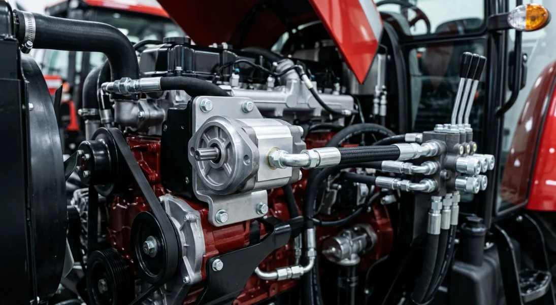
Types of Hydraulic Pumps Compatible with Tractors
Three pump designs dominate tractor applications. Each has distinct advantages depending on your flow requirements, budget, and the implements you plan to run.
Gear pumps are the most common choice for PTO-driven auxiliary systems due to their simplicity, durability, and low cost. Vane pumps offer quieter operation but are less tolerant of contaminated fluid. Piston pumps deliver the highest pressure and flow but come at a premium price point.
| Pump Type | Flow Rate (GPM) | Max PSI | Best For | Avg. Cost |
|---|---|---|---|---|
| Gear Pump | 4–22 GPM | 2,500–3,000 | Log splitters, augers | $150–$400 |
| Vane Pump | 5–15 GPM | 2,000–2,500 | Mowing decks, light loaders | $200–$500 |
| Piston Pump | 8–40 GPM | 3,000–5,000 | Excavator arms, heavy implements | $500–$1,500 |
For most tractor owners adding a rear remote hydraulic valve or running a single implement, a two-stage gear pump in the 11–16 GPM range hits the sweet spot of performance and value.
Signs Your Tractor Needs an Additional Hydraulic Pump
Slow cylinder response is the most obvious indicator. If your loader takes noticeably longer to lift when you're also running a rear remote, your stock pump can't keep up with simultaneous demand.
Inability to run multiple remotes at adequate speed is another clear sign. Stock hydraulic systems on compact tractors typically deliver 6–9 GPM, which gets divided among all active circuits. Adding a grapple, thumb, or tilt function often pushes demand beyond what the factory pump provides.
Overheating tractor hydraulic fluid signals that your system is working beyond its capacity. If your hydraulic fluid temperature consistently exceeds 180°F during normal operation, the pump is either undersized or the system is starved for flow.
Tools, Parts, and PTO Hydraulic Pump Kit Checklist
Essential Components for Installation
A complete PTO hydraulic pump kit typically includes the pump, PTO shaft coupler, mounting bracket, and sometimes a basic control valve. However, most kits require additional components for a proper installation.
You'll need a hydraulic reservoir tank, suction strainer, return-line filter (10-micron recommended), pressure relief valve, hydraulic hose fittings in the correct size and thread type, and a rear remote hydraulic valve if you're plumbing for implement use. Don't forget the small items: O-rings, JIC caps for unused ports, and a breather cap for the reservoir.
Tools Required
| Tool | Purpose |
|---|---|
| Torque wrench | Tightening fittings to spec |
| Flare nut wrenches | Hydraulic line connections without rounding |
| Thread sealant (Loctite 545) | Leak prevention on NPT fittings |
| Hydraulic pressure gauge (0–5,000 PSI) | System testing and relief valve adjustment |
| Drill + step bit | Mounting bracket holes in frame |
| Safety glasses and gloves | Personal protection from pressurized fluid |
| Tube cutter or hacksaw | Cutting hydraulic tubing to length |
| Deburring tool | Cleaning cut tube ends for leak-free connections |
Choosing the Right Pump Size for Your Tractor
Pump sizing comes down to matching GPM and PSI to your implement's demand. Every hydraulic cylinder and motor has a rated flow requirement. Exceeding it wastes energy and generates heat. Falling short means sluggish performance.
Here's a real-world example: A John Deere 3025E owner adding a rear remote hydraulic valve for a grapple and log splitter installed a 16 GPM two-stage gear pump (Haldex/Barnes model). The two-stage design delivers high flow at low pressure for fast cylinder extension, then automatically shifts to low flow at high pressure for the power stroke. This matched the grapple's need for quick cycle times and the splitter's need for 2,500+ PSI splitting force.
The general formula is straightforward. Calculate your cylinder's volume in cubic inches, divide by 231 to convert to gallons, then multiply by your desired cycles per minute. That gives you the GPM requirement. Add 10–15% for system losses.
Step-by-Step Hydraulic Pump Installation Process
Step 1 – Mounting the Pump to the PTO or Engine
PTO-driven installations are the most common for auxiliary hydraulic systems because they require no permanent engine modifications. The pump mounts to a bracket on the tractor's drawbar or three-point hitch frame and connects to the PTO shaft via a splined coupler.
Belt-driven setups tap into the engine's crankshaft pulley and run continuously. This works well for tractors that need constant hydraulic flow regardless of PTO engagement, but requires careful belt alignment and tensioning. Direct engine-mount pumps bolt to the timing cover or accessory drive and are common on older tractors without live PTO.
Regardless of method, alignment is critical. Misalignment of even 2–3 degrees causes premature seal failure and shaft wear. Use a straight edge across the coupler faces and shim the mounting bracket until the pump shaft runs true with the drive source.
Step 2 – Installing the Hydraulic Reservoir
Size your reservoir using the 3x rule: the tank should hold at least three times the pump's GPM rating in gallons. For a 16 GPM pump, that means a minimum 48-gallon reservoir. In practice, a 15–20 gallon tank works for most PTO pump setups because the system volume (hoses, cylinders, valve) adds additional capacity.
Mount the reservoir above the pump's inlet whenever possible. Gravity-fed suction reduces cavitation risk and extends pump life. Position the tank where it's protected from implement contact but accessible for fluid level checks.
Install a breather cap on the reservoir to prevent vacuum lock during pump operation. The return line should enter below the fluid level to prevent foaming, and the suction port should sit at least 2 inches above the tank bottom to avoid pulling settled contaminants into the pump.
Step 3 – Running Hydraulic Hose Fittings and Lines
Select hose diameter based on your pump's flow rate. For a 16 GPM system, 3/4-inch hose on the suction side and 1/2-inch hose on the pressure side keeps fluid velocity within the recommended 15–20 ft/s range. Undersized suction lines are the number one cause of pump cavitation and premature failure.
Route all hydraulic hose fittings away from exhaust manifolds, moving PTO shafts, and sharp edges. Use clamps every 18–24 inches to prevent hose whip under pressure spikes. Leave enough slack at connection points to allow for hose movement without pulling on fittings.
Use JIC 37-degree flare fittings wherever possible. They're reusable, reliable, and don't require thread sealant. ORB (O-Ring Boss) fittings are the next best choice for ports that accept them. Reserve NPT fittings for reservoir ports and low-pressure connections only, and always apply Loctite 545 or PTFE paste (not tape) to NPT threads.
Step 4 – Connecting the Rear Remote Hydraulic Valve
Mount the control valve in an accessible location, typically on the rear fender or near the three-point hitch. The valve needs to be reachable from the operator's seat or standing position at the rear of the tractor.
Plumb the pressure (supply) line from the pump outlet to the valve's inlet port. Run the return line from the valve's tank port back to the reservoir. If you're installing a multi-spool rear remote hydraulic valve, each spool controls one implement circuit. The supply and return are shared internally within the valve body.
Install detent positions on spools that will operate single-acting cylinders (like a log splitter) so the valve stays engaged without holding the lever. Float position is essential for implements like box blades or snow plows that need to follow ground contour.
Step 5 – Filling with Tractor Hydraulic Fluid and Bleeding the System
Use Universal Tractor Fluid (UTF) meeting J20C/303 specifications unless your tractor manufacturer specifies otherwise. John Deere requires Hy-Gard, Kubota recommends UDT (Universal Dynamic Tractor Fluid), and Case IH specifies Hy-Tran. Using the wrong tractor hydraulic fluid can damage seals and void warranties on connected components.
Fill the reservoir to the full mark with the cylinders retracted. Start the pump at low RPM (idle PTO speed) and let it circulate for 2–3 minutes without actuating any valves. This primes the pump and fills the lines. Then slowly cycle each cylinder through its full stroke 5–6 times to purge trapped air.
Recheck the reservoir level after bleeding. Air displacement from the lines will drop the fluid level significantly. Top off and repeat the cycling process until cylinder movement is smooth and consistent with no spongy feel or jerking.
Step 6 – Testing Under Load
Connect a hydraulic pressure gauge to the test port downstream of the pump (before the valve). Set the pressure relief valve to your system's working pressure, typically 2,500 PSI for most implement applications.
Stall-test each cylinder by running it to the end of its stroke and holding momentarily. The pressure gauge should climb to the relief valve setting and hold steady. If pressure fluctuates or won't reach the set point, you have an internal leak in the valve or cylinder.
Inspect every hydraulic hose fitting, connection point, and the pump shaft seal for leaks while the system is under full pressure. Run your implements at full demand for 15–20 minutes, then check the fluid temperature. It should stabilize below 180°F. If it runs hotter, you may need a larger reservoir or an oil cooler.
Common Hydraulic System Installation Mistakes to Avoid
Undersizing Hoses and Fittings
This is the most frequent mistake in DIY hydraulic system installation projects. Fluid velocity increases exponentially as hose diameter decreases. Exceeding 20 ft/s in pressure lines or 4 ft/s in suction lines causes turbulence, heat buildup, and excessive pressure drop.
| Hose ID | Max Recommended GPM | Velocity at Max GPM |
|---|---|---|
| 3/8" | 8 GPM | 18 ft/s |
| 1/2" | 13 GPM | 17 ft/s |
| 3/4" | 28 GPM | 16 ft/s |
| 1" | 50 GPM | 16 ft/s |
If your pump delivers 16 GPM and you're using 1/2-inch pressure hose, you're already over the recommended maximum. The result is excessive heat, pressure loss at the cylinder, and shortened hose life. Step up to 3/4-inch hose for anything above 13 GPM.
Skipping the Pressure Relief Valve
A hydraulic system without a pressure relief valve is a ticking time bomb. When a cylinder reaches the end of its stroke or an implement stalls, pressure spikes instantly. Without a relief valve, that pressure has nowhere to go except through the weakest point in your system, which is usually a hose fitting or the pump's internal seals.
Burst hydraulic hoses at 2,500+ PSI can inject fluid through skin, causing serious injury or death. Always install a relief valve rated for your pump's maximum output and set it 200–300 PSI above your normal working pressure. Test it annually with a pressure gauge.
Using Incorrect Tractor Hydraulic Fluid
Mixing different tractor hydraulic fluid types causes seal degradation, additive incompatibility, and sludge formation. Automotive ATF is not a substitute for tractor hydraulic fluid, even though some older manuals suggest it. Modern tractor hydraulic systems use fluid that also lubricates wet brakes and transmissions, requiring specific friction modifiers that ATF doesn't contain.
Viscosity matters too. Using fluid that's too thin for your climate causes internal pump leakage and reduced efficiency. Too thick, and the pump cavitates on cold starts. Check your tractor's manual for the correct ISO viscosity grade, typically ISO 46 or ISO 68 depending on operating temperature range.
Real-World Installation Examples
Case Study – Adding a PTO Hydraulic Pump Kit to a Kubota L2501
A Kubota L2501 owner needed auxiliary hydraulics to run a 25-ton log splitter and a rear-mounted grapple independently of the tractor's stock system. The stock pump delivers only 6.9 GPM, which is inadequate for simultaneous implement use.
The installation used a 16 GPM two-stage gear pump (approximately $280) driven by the rear 540 RPM PTO, a Prince RD-2575 two-spool directional valve ($185), a 15-gallon vertical reservoir ($120), and 50 feet of 1/2-inch and 3/4-inch hydraulic hose with JIC fittings ($210). A 10-micron return filter ($45) and adjustable pressure relief valve ($35) completed the system.
Total cost came to approximately $875 in parts, plus a weekend of labor. The system now delivers full log-splitting force in under 8 seconds cycle time and operates the grapple with fast, responsive movement. The owner reported the tractor hydraulic fluid temperature stays below 160°F during sustained splitting sessions with the 15-gallon reservoir providing adequate cooling capacity.
Case Study – Hydraulic System Installation on a Ford 3000 Vintage Tractor
Vintage tractors present unique challenges for hydraulic system installation. A Ford 3000 owner wanted to add a rear remote hydraulic valve for a modern bale spear, but the tractor's original system uses a non-standard pump configuration and outdated fitting types.
The main challenge was that the Ford 3000's internal hydraulic pump shares fluid with the transmission and rear axle. Tapping into this system risks starving the power steering and lift arms. The solution was a completely independent auxiliary system driven by a belt off the engine's crankshaft pulley.
The owner installed an 11 GPM gear pump with a custom bracket, a single-spool Wolverine MB-21 valve, and a 10-gallon reservoir mounted behind the seat. Adapter fittings from BSP (British Standard Pipe) to JIC were needed for the few connections that interfaced with original components. Total investment was approximately $650, and the system has operated reliably for three seasons handling round bales weighing up to 1,200 lbs.
Frequently Asked Questions (FAQ)
How much does it cost to add a hydraulic pump to a tractor?
A basic PTO hydraulic pump kit with a single valve and reservoir runs $300–$800 for parts. More complex installations with multi-spool rear remote hydraulic valves, larger reservoirs, and premium components can reach $1,500–$2,000. Professional installation adds $500–$1,000 in labor depending on your region and the complexity of the setup.
Can I run a hydraulic pump off my tractor's PTO?
Yes, this is the most common method for adding auxiliary hydraulics to a tractor. You'll need a pump rated for either 540 or 1000 RPM PTO speed (match your tractor's output) and an appropriate splined coupler. Live PTO is preferred so the pump operates independently of the clutch. If your tractor has a transmission-driven PTO, the pump stops whenever you depress the clutch.
What type of tractor hydraulic fluid should I use?
Use Universal Tractor Fluid (UTF) meeting J20C or 303 specifications for most applications. If your tractor is under warranty or you're connecting to the existing system, use the manufacturer's specified fluid: John Deere Hy-Gard, Kubota UDT, Case IH Hy-Tran, or equivalent. For standalone auxiliary systems, any quality UTF from brands like Traveller, Rotella, or Mobil works well.
How many GPM do I need for a rear remote hydraulic valve?
Most single-remote implements like log splitters, bale spears, and simple grapples need 5–12 GPM. If you're running multiple remotes simultaneously or operating high-demand attachments like tree shears or brush cutters, plan for 15–25 GPM. Calculate your actual need based on cylinder volume and desired cycle time rather than guessing.
Do I need a separate reservoir or can I tap into the existing system?
A separate reservoir is strongly recommended for PTO-driven pump installations. Tapping into the tractor's existing hydraulic system risks overloading the stock pump, starving the power steering or three-point hitch, and introducing contamination between systems. The only exception is if your tractor manufacturer offers a factory auxiliary hydraulic kit designed to share the existing reservoir.
How do I prevent hydraulic hose fittings from leaking?
Start by matching fitting types correctly. Never mix JIC with ORB or NPT without proper adapters. Torque JIC fittings to the manufacturer's specification (typically 1 to 1-1/4 flats past finger-tight for steel fittings). Apply Loctite 545 or PTFE paste to NPT threads only. Never use Teflon tape on JIC or ORB fittings, as it can shred and contaminate the system. Inspect all fittings after the first hour of operation and re-torque if needed.



