

The gerotor hydraulic motor represents a remarkably efficient power conversion mechanism characterized by a minimal moving-part count — typically limited to two primary rotating elements — capable of delivering substantial torque output at exceptionally low rotational velocities. Unlike conventional reciprocating engines that rely on intricate valve timing mechanisms, piston assemblies, and camshaft configurations, the gerotor design achieves hydraulic-to-mechanical energy conversion through an elegantly simplified architecture. This operational principle has established the gerotor motor as a critical actuator across a broad spectrum of industrial applications, including compact excavation machinery and conveyor drive systems.
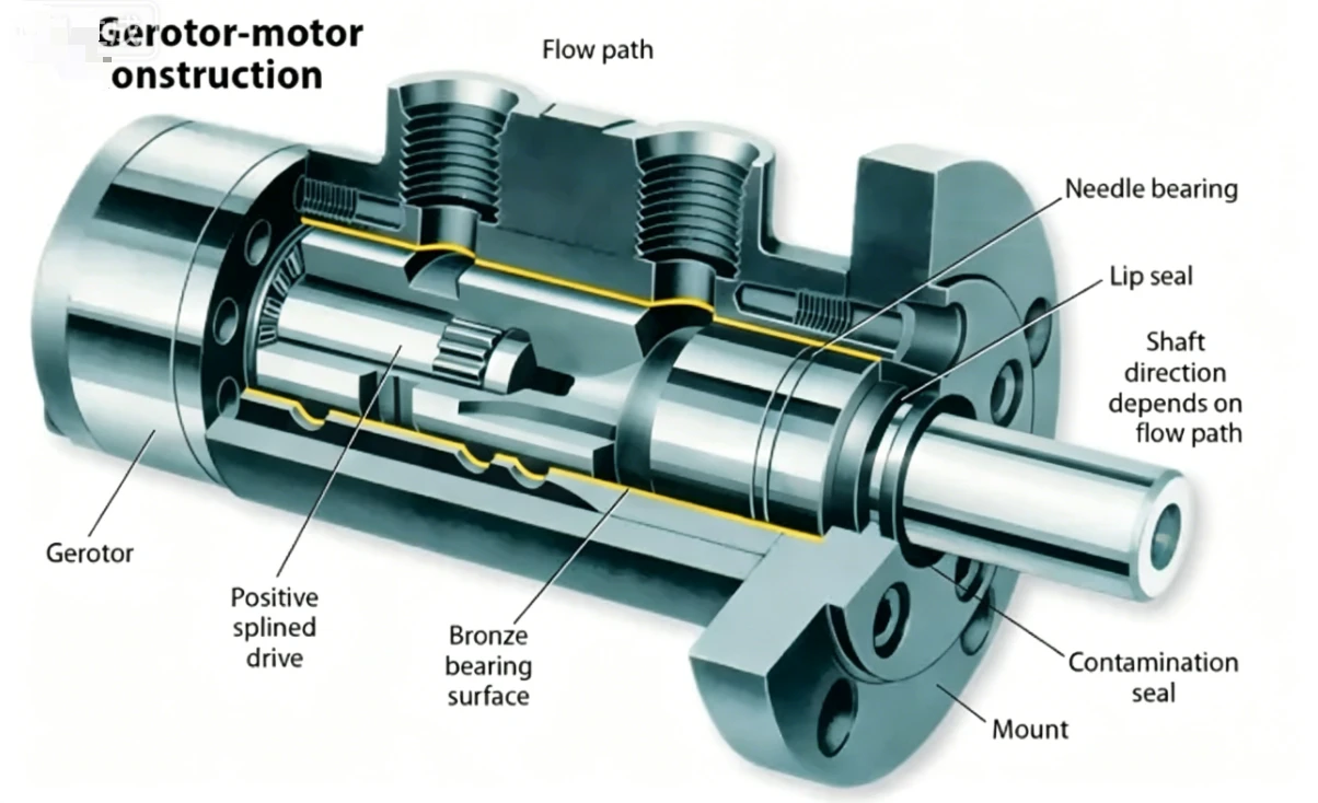
Understanding the gerotor pump mechanism in reverse reveals one of hydraulic engineering's most efficient solutions for low speed high torque motor applications. In this guide, we break down the orbital motor design, explain hydraulic fluid displacement principles, and show exactly how inner outer gear rotation converts fluid pressure into usable mechanical work.
What Is a Gerotor Hydraulic Motor?
Definition and Core Concept
A gerotor — short for "generated rotor" — is a positive-displacement device built around two concentric gears. An inner gear rotates within an outer gear, creating expanding and contracting fluid chambers that convert hydraulic pressure into smooth mechanical rotation.
The principle is elegantly simple. As pressurized hydraulic fluid enters the expanding chambers, it pushes the inner gear along an orbital path. That orbital motion is then translated into concentric shaft rotation, delivering high torque at low speed without the complexity of pistons or sliding vanes.
Gerotor vs. Geroler — Key Distinction
A true gerotor uses direct gear-on-gear contact between the inner star and the outer ring. The tooth profiles are conjugate curves that maintain a continuous seal between adjacent chambers.
A geroler replaces the fixed teeth of the outer ring with individual rollers seated in the housing. This roller-element variant reduces friction and wear at the contact points, making it better suited for higher-pressure and longer-life applications. Both share the same orbital motor design principle, but gerolers typically achieve higher volumetric efficiency and longer service intervals.
Internal Components and Orbital Motor Design
Inner Gear (Star)
The star-shaped inner rotor features N teeth (commonly 4 to 7) with a precisely machined profile. Rather than spinning on its own center, this gear orbits eccentrically inside the ring gear, sweeping through displacement chambers as it moves.
The tooth geometry directly determines the motor's displacement volume per revolution. Wider teeth and greater face width increase displacement, which in turn increases torque output at any given operating pressure.
Outer Gear (Ring)
The ring gear contains N+1 teeth — always one more than the inner gear. This single-tooth difference is the key to the gerotor's function, creating discrete chambers that progressively expand and contract as the gears mesh.
In most orbital motor designs, the outer gear remains stationary within the housing. The inner gear orbits against it, and the changing volume between meshing teeth is what enables hydraulic fluid displacement and torque generation.
Housing, Ports, and Commutation
A valve plate or manifold disc sits adjacent to the gear set and acts as the motor's fluid distribution brain. It contains precisely machined passages that direct pressurized fluid to the correct expanding chambers while simultaneously opening contracting chambers to the return line.
This commutation happens passively through the geometry of the port timing. As the inner gear orbits, different chambers align with high-pressure and low-pressure passages in sequence, maintaining continuous and smooth rotation without electronic controls.
Output Shaft and Drive Link
The inner gear's orbital motion cannot drive a load directly — it traces a circular path rather than spinning on a fixed axis. A cardan shaft or splined coupling link connects the orbiting gear to the output shaft, converting the eccentric motion into true concentric rotation.
This drive link must accommodate the eccentricity of the orbit while transmitting full torque. Hardened alloy steel construction and precise spline fits ensure durability under the high loads typical of low speed high torque motor applications.
| Component | Function | Material |
|---|---|---|
| Inner gear (star) | Orbits to create displacement | Hardened steel |
| Outer gear (ring) | Stationary or slow-rotating housing element | Ductile iron / steel |
| Valve plate | Directs fluid to correct chambers | Hardened steel |
| Drive link / cardan shaft | Converts orbital motion to shaft rotation | Alloy steel |
| Shaft seals | Prevent external leakage | Nitrile / Viton |
How Hydraulic Fluid Displacement Creates Rotation
Step-by-Step Operating Cycle
The operating cycle begins when pressurized hydraulic fluid enters through the inlet port and passes through the valve plate into the expanding chambers between the inner and outer gears. This fluid pressure acts on the exposed tooth surfaces of the inner gear, pushing it along its eccentric orbital path.
As the inner gear advances, chambers on the inlet side continue to expand and fill with fluid, while chambers on the opposite side contract and force spent fluid out through the return port. This continuous process of filling and emptying creates an uninterrupted torque output with minimal pulsation.
One complete orbit of the inner gear — during which every chamber has expanded and contracted once — constitutes one full revolution of the output shaft. The cycle then repeats seamlessly for as long as pressurized flow is supplied.
Inner Outer Gear Rotation Relationship
The speed relationship between the gears is governed by the tooth count difference. For every full orbit the inner gear makes around the inside of the ring, the output shaft completes exactly one revolution. This 1:1 orbit-to-revolution ratio is inherent to the single-tooth-difference geometry.
Because the displacement volume per revolution is large relative to the motor's physical size, the resulting shaft speed is inherently low for a given flow rate. This is what gives gerotor motors their characteristic low speed high torque motor behavior without requiring external gear reduction.
Displacement Volume Calculation
The volumetric displacement per revolution depends on the tooth geometry, the eccentricity between gear centers, and the axial face width of the gear set. The general relationship is:
Vd = 2 × π × e × D × W × N
Where e is eccentricity, D is the pitch diameter, W is the face width, and N is the number of teeth on the inner gear. Manufacturers optimize these parameters to achieve target displacement values ranging from 50 to 800 cm³/rev.
| Parameter | Symbol | Typical Range |
|---|---|---|
| Number of inner gear teeth | N | 4 – 7 |
| Number of outer gear teeth | N + 1 | 5 – 8 |
| Eccentricity | e | 2 – 6 mm |
| Displacement per rev | Vd | 50 – 800 cm³/rev |
| Operating pressure | P | 70 – 250 bar |
Gerotor Pump Mechanism vs. Motor Mode
Reversibility Principle
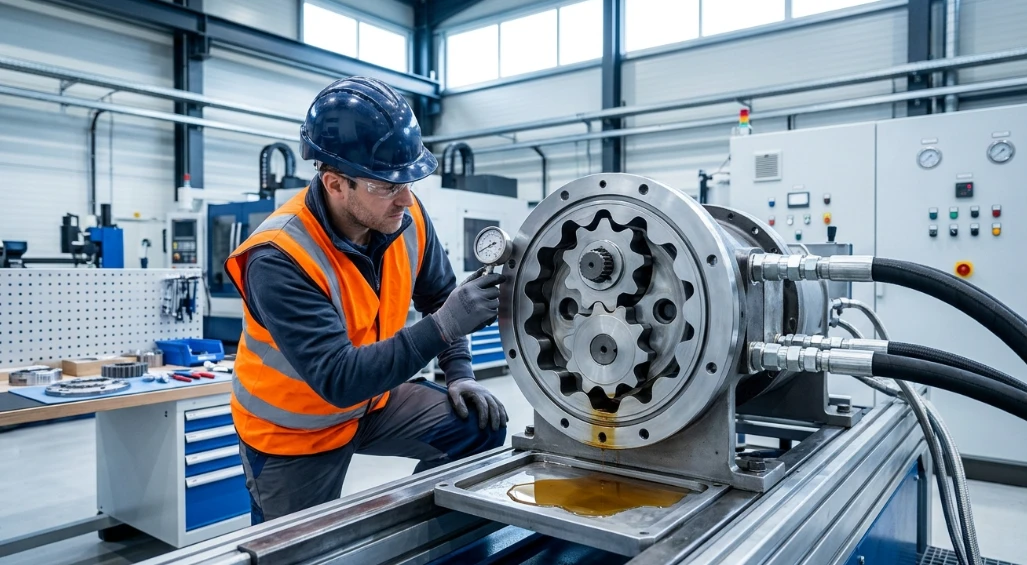
The gerotor pump mechanism and the gerotor motor share identical internal geometry. The difference lies solely in the energy input. When you drive the shaft mechanically, the gear set displaces fluid and the device functions as a pump. When you supply pressurized fluid externally, the gear set drives the shaft and the device functions as a motor.
This reversibility is a fundamental characteristic of all positive-displacement hydraulic machines. In practice, many gerotor units are marketed specifically as either pumps or motors, with port sizing, bearing selection, and seal orientation optimized for the intended mode of operation.
Efficiency Considerations in Motor Mode
Overall efficiency of a gerotor motor typically falls between 85% and 92%, combining both volumetric and mechanical losses. Volumetric efficiency accounts for internal leakage past the gear tips and valve plate, while mechanical efficiency reflects friction in the bearings, seals, and gear mesh.
Several factors influence efficiency in motor mode. Higher operating pressure increases internal leakage, reducing volumetric efficiency. Elevated fluid temperature lowers viscosity, which also increases leakage. Conversely, excessively cold fluid raises viscous drag and hurts mechanical efficiency. The optimal operating window balances these competing effects.
Performance Characteristics and Applications
Torque-Speed-Pressure Relationship
Output torque scales linearly with both displacement and pressure differential. The theoretical torque formula is: T = (Vd × ΔP) / (2π), where Vd is displacement in cubic meters per revolution and ΔP is the pressure drop across the motor in Pascals.
Speed is inversely proportional to displacement at a constant flow rate: n = Q / Vd, where Q is the volumetric flow rate. This means selecting a larger displacement motor yields more torque but lower speed for the same hydraulic power input — the defining tradeoff in orbital motor design.
Common Applications of Low Speed High Torque Motors
Gerotor motors excel wherever high torque at low rotational speed is needed in a compact package. Skid-steer and tracked vehicle wheel drives rely on them for direct-drive propulsion without gearboxes. Agricultural implements such as seed drills and fertilizer spreaders use them for precise, low-speed rotation.
Industrial applications include conveyor roller drives, plastic injection molding screw drives, winches, and auger systems. Their smooth low-speed operation and bi-directional capability make them particularly well-suited for positioning and material handling tasks.
| Application | Typical Displacement | Speed Range | Torque Range |
|---|---|---|---|
| Skid-steer wheel drive | 400 – 800 cm³/rev | 50 – 150 RPM | 300 – 900 Nm |
| Conveyor drive | 200 – 500 cm³/rev | 30 – 100 RPM | 200 – 600 Nm |
| Auger / mixer | 100 – 300 cm³/rev | 80 – 250 RPM | 100 – 400 Nm |
| Winch motor | 500 – 800 cm³/rev | 10 – 60 RPM | 500 – 1200 Nm |
Advantages and Limitations
Why Choose a Gerotor Motor
The gerotor's greatest strength is simplicity. With only two primary moving parts — the inner gear and the drive link — there are fewer components to wear or fail compared to piston or vane motors. This translates to high reliability and lower maintenance costs over the motor's service life.
Compact physical size relative to torque output makes gerotor motors ideal for space-constrained installations. They deliver excellent low-speed smoothness with minimal torque ripple, high starting torque even from standstill, and full bi-directional capability without requiring external valving changes.
Known Limitations
Gerotor motors have a lower maximum speed ceiling than axial piston or external gear motors, typically topping out around 250–400 RPM depending on displacement. At very low speeds (below approximately 10 RPM), torque pulsation increases and efficiency drops noticeably.
Maximum operating pressure is generally limited to 250 bar, which restricts peak torque compared to piston motors rated for 350–450 bar. The tight clearances between gear profiles also make these motors sensitive to particulate contamination in the hydraulic fluid.
| Advantage | Limitation |
|---|---|
| Few moving parts — high reliability | Lower max RPM than gear or piston motors |
| Excellent low-speed smoothness | Efficiency decreases below ~10 RPM |
| High torque density | Max pressure typically ≤ 250 bar |
| Compact envelope | Sensitive to fluid contamination |
| Bi-directional without valving changes | Higher internal leakage at elevated temps |
Maintenance and Fluid Requirements
Recommended Hydraulic Fluids
Gerotor motors perform best with mineral-based hydraulic oils in the ISO VG 32 to VG 68 range, maintaining an operating viscosity between 16 and 100 cSt at working temperature. Viscosity below 16 cSt accelerates internal leakage and wear, while viscosity above 100 cSt increases pressure drop and reduces mechanical efficiency.
Fluid cleanliness is critical. A target cleanliness class of ISO 18/16/13 or better protects the tight gear-to-housing clearances from abrasive wear. Biodegradable fluids (HEES, HETG) and water-glycol fluids are compatible with most gerotor motors, provided seal materials are verified against the fluid type.
Common Failure Modes and Prevention
The most frequent failure mode is progressive wear of the inner gear tooth tips and outer ring profile caused by contaminated fluid. This wear increases internal leakage, reducing torque output and efficiency gradually over time. Monitoring case drain flow provides an early warning of internal wear progression.
Seal degradation from excessive temperature or chemical incompatibility leads to external leakage. Scheduled seal replacement at manufacturer-recommended intervals — typically every 4,000 to 6,000 operating hours — prevents unplanned downtime. Keeping fluid temperature below 80°C and ensuring adequate filtration are the two most effective preventive measures.
FAQ
How does a gerotor motor differ from a vane motor?
A gerotor motor uses meshing gear profiles to create displacement chambers, while a vane motor relies on sliding vanes extending from a rotor into a cam ring. Gerotors excel at lower speeds and offer higher torque density in a more compact package. Vane motors typically achieve higher speeds but produce less torque per unit of displacement.
Can a gerotor motor run in both directions?
Yes. Reversing the pressure and return port connections reverses the shaft rotation without any internal modifications. This bi-directional capability is inherent to the symmetric orbital motor design and makes gerotors well-suited for applications like winches and reversible conveyors.
What determines the torque output of a gerotor motor?
Torque output is the product of the motor's displacement per revolution and the pressure differential across the inlet and outlet ports, minus friction losses. Increasing either displacement or system pressure raises torque proportionally, up to the motor's rated limits.
Why is the gerotor classified as a low speed high torque motor?
The single-tooth difference between the inner and outer gears creates a large volumetric displacement per orbit. This means that for a given flow rate, the shaft turns slowly but with substantial force. The geometry inherently favors torque production over speed, eliminating the need for external gear reduction in most applications.
How is the gerotor pump mechanism related to the motor?
They share identical internal geometry and operating principles. When you drive the shaft mechanically, the gear set displaces fluid and the unit acts as a pump. When you supply pressurized fluid to the ports, the gear set drives the shaft and the unit acts as a motor. The gerotor pump mechanism is simply the motor operating in reverse energy flow.
What maintenance extends gerotor motor life?
Maintaining fluid cleanliness to ISO 18/16/13 or better is the single most impactful practice. Beyond filtration, monitor case drain flow regularly to detect internal wear early, replace shaft seals at recommended intervals, and keep hydraulic fluid temperature within the 40–80°C operating window. These steps collectively maximize service life and maintain peak efficiency of the hydraulic fluid displacement process.



