

Every time a 50-ton excavator pivots effortlessly on muddy terrain, a hydraulic track motor is converting fluid pressure into raw rotational force — here's exactly how that engineering happens beneath the heavy equipment undercarriage. Understanding this mechanism reveals why crawler machines dominate construction, mining, and forestry operations worldwide.
Hydraulic track motors are the hidden powerhouses tucked inside every tracked machine's undercarriage. They transform pressurized hydraulic fluid into the relentless torque that moves steel tracks across the roughest ground on earth. In this guide, we'll break down every component, working principle, and performance factor that makes the track drive system function.
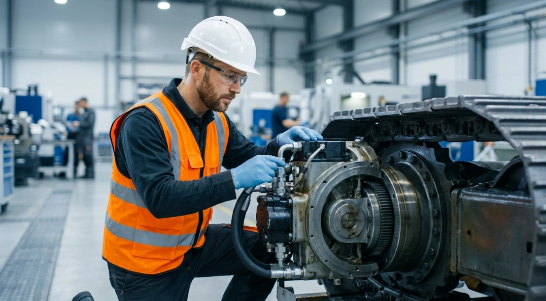
What Is a Hydraulic Track Motor?
Definition and Core Function
A hydraulic track motor is a rotary actuator that converts hydraulic fluid pressure into mechanical torque, driving the crawler tracks on heavy machinery. It functions as the final link between the machine's hydraulic pump and the ground, translating fluid energy into controlled movement.
Unlike electric motors or internal combustion engines, hydraulic track motors generate enormous force in a compact package. Their ability to produce high hydraulic motor torque output at low speeds makes them ideal for moving heavy loads across uneven terrain without stalling.
Where Track Drive Systems Are Used
Track drive systems appear across a wide range of heavy equipment. Excavators, bulldozers, compact track loaders, drilling rigs, and forestry mulchers all rely on hydraulic track motors for propulsion.
Any application where wheeled locomotion fails — steep grades, soft soil, rocky surfaces, or extreme load requirements — benefits from a track drive system. The heavy equipment undercarriage distributes machine weight over a larger surface area, and the hydraulic motor provides the torque needed to keep those tracks turning under load.
Key Components of a Hydraulic Track Motor
Internal Parts Breakdown
Every hydraulic track motor contains a precise assembly of components working together under extreme pressure. Understanding each part clarifies how the piston displacement mechanism converts fluid energy into rotation.
| Component | Function |
|---|---|
| Cylinder Block | Houses pistons and rotates with the output shaft |
| Pistons | Convert hydraulic fluid pressure into linear force |
| Swash Plate / Cam Ring | Translates linear piston motion into rotation |
| Valve Plate | Directs fluid flow to correct piston chambers |
| Output Shaft | Delivers hydraulic motor torque output to the sprocket |
| Seals & Bearings | Maintain pressure and reduce friction |
| Planetary Gear Reduction | Multiplies torque for heavy-load movement |
How the Piston Displacement Mechanism Creates Motion
The piston displacement mechanism is the heart of every hydraulic track motor. Pressurized fluid enters individual piston bores within the cylinder block, forcing each piston outward against an angled swash plate or cam surface.
Because the swash plate sits at a fixed angle relative to the cylinder block, the linear push of each piston creates a tangential force. This force rotates the cylinder block and output shaft continuously as pistons fire in sequence around the block.
The displacement volume — measured in cubic centimeters per revolution — determines how much fluid is consumed per rotation and directly influences the balance between speed and torque. Larger displacement means more hydraulic motor torque output at lower rotational speeds.
Step-by-Step Working Principle
Stage 1 — Hydraulic Fluid Pressurization
The process begins at the hydraulic pump, typically driven by the machine's diesel engine. The pump draws fluid from the reservoir and pressurizes it to operating levels between 250 and 450 bar.
This high-pressure hydraulic fluid travels through directional control valves that determine which track motor receives flow and in which direction. The operator's joystick or pedal commands dictate valve position, controlling both speed and direction of travel.
Stage 2 — Piston Displacement and Rotation
High-pressure fluid enters the motor through the valve plate, which routes it to specific piston bores on the high-pressure side of the cylinder block. As fluid fills each bore, it pushes the piston outward with tremendous force.
Each piston's tip rides against the angled swash plate surface. The angle converts the piston's linear thrust into a rotational moment around the shaft centerline. Multiple pistons — typically seven or nine — fire in overlapping sequence, producing smooth and continuous rotation.
This is the piston displacement mechanism in action: fluid pressure becomes linear force, linear force becomes angular momentum, and the cylinder block spins.
Stage 3 — Torque Multiplication Through Gear Reduction
Raw motor speed is far too high and torque too low to drive a track sprocket directly. Planetary gear reduction solves this problem by trading speed for force.
A planetary gear set — consisting of a sun gear, planet gears, and a ring gear — sits between the motor output shaft and the final drive sprocket. Typical reduction ratios range from 40:1 to 100:1, multiplying hydraulic motor torque output dramatically while reducing output speed to the 0–5 km/h range needed for tracked travel.
This gear reduction stage is what allows a relatively small motor to move a 50-ton machine up a grade.
Stage 4 — Return Flow and Continuous Cycle
As each piston passes the low-pressure side of the valve plate, spent fluid exits the cylinder bore at reduced pressure. This return fluid flows back through the system to the hydraulic reservoir.
The reservoir allows the fluid to cool, settle, and pass through filtration before the pump draws it back into the high-pressure circuit. This cycle repeats thousands of times per minute, creating the smooth and continuous track movement operators depend on.
Types of Hydraulic Track Motors
Comparison Table
Not all track motors use the same internal mechanism. The choice depends on required torque, operating conditions, and machine size.
| Type | Displacement | Torque Output | Best For |
|---|---|---|---|
| Axial Piston | Variable | High | Excavators, large dozers |
| Radial Piston | Fixed/Variable | Very High | Heavy-duty mining equipment |
| Gear Motor | Fixed | Low–Medium | Compact track loaders |
| Vane Motor | Fixed | Low | Light-duty applications |
Axial piston motors dominate the track drive system market due to their excellent power density and variable displacement capability. Radial piston designs excel where maximum torque at very low speed is non-negotiable, such as in mining shovels and large drilling rigs.
Fixed vs. Variable Displacement Motors
Variable displacement motors allow the operator or control system to adjust the swash plate angle during operation. Increasing the angle raises displacement, producing more torque at lower speed. Decreasing it allows higher speed with less torque — essentially giving the machine a two-speed travel mode.
Fixed displacement motors offer mechanical simplicity and greater durability since there are fewer moving parts and no servo mechanism to fail. They're common in compact equipment where a single operating speed range is acceptable.
The trade-off is clear: variable displacement provides versatility and efficiency across varying load conditions, while fixed displacement delivers reliability and lower manufacturing cost.
Performance Factors and Specifications
Critical Performance Metrics
Selecting the right hydraulic track motor requires matching specifications to application demands. The following parameters define motor capability.
| Parameter | Typical Range | Impact |
|---|---|---|
| Operating Pressure | 250–450 bar | Determines max force |
| Displacement | 20–200 cc/rev | Controls speed vs. torque |
| Torque Output | 500–50,000 Nm | Dictates load capacity |
| Volumetric Efficiency | 92–97% | Affects fuel economy |
| Max Speed | 1,500–4,000 RPM | Limits travel speed |
How Hydraulic Fluid Pressure Affects Output
The relationship between hydraulic fluid pressure and motor output follows a direct formula: torque equals pressure multiplied by displacement divided by 2π. Doubling system pressure doubles the hydraulic motor torque output, assuming displacement remains constant.
In practice, this means a motor operating at 350 bar with 100 cc/rev displacement produces significantly more torque than the same motor at 250 bar. System designers select operating pressure based on the maximum load the machine must handle, including grade climbing and drawbar pull requirements.
Volumetric efficiency also plays a critical role. Internal leakage past pistons and valve plates means not all pressurized fluid contributes to useful work. Higher-quality manufacturing tolerances yield efficiencies above 95%, translating directly to better fuel economy and more responsive track drive system performance.
Maintenance and Common Failure Points
Signs of Track Motor Wear
Recognizing early symptoms of track motor degradation prevents catastrophic failure and costly downtime. The most common warning sign is a gradual loss of drive power — the machine struggles on grades it previously climbed easily.
Overheating at the motor housing indicates internal friction from worn bearings or insufficient lubrication. Excessive noise, particularly a knocking or whining sound from the heavy equipment undercarriage, often points to cavitation or damaged pistons.
Visible hydraulic fluid leaks around the motor case drain or shaft seal demand immediate attention. Even small external leaks suggest internal seal degradation that reduces the piston displacement mechanism efficiency and contaminates the surrounding undercarriage components.
Preventive Maintenance Schedule
Following a structured maintenance program extends track motor life and protects your investment in the entire hydraulic system.
| Interval | Action |
|---|---|
| Every 250 hours | Check fluid level and condition |
| Every 500 hours | Inspect seals and hose connections |
| Every 1,000 hours | Replace hydraulic filters |
| Every 2,000 hours | Flush system and analyze fluid |
| Every 5,000 hours | Full motor inspection or rebuild |
Fluid cleanliness is the single most important factor in track motor longevity. Contaminated hydraulic oil accelerates wear on pistons, valve plates, and bearings far faster than normal operating loads. Maintaining fluid to ISO 18/16/13 cleanliness standards or better dramatically extends service life.
Frequently Asked Questions (FAQ)
How long do hydraulic track motors last?
Hydraulic track motors typically last between 5,000 and 10,000 operating hours with proper maintenance. Actual lifespan depends heavily on load conditions, hydraulic fluid cleanliness, operating temperature, and whether the machine is regularly pushed beyond rated capacity. Machines operating in clean, moderate conditions often exceed 10,000 hours before requiring a rebuild.
What causes a hydraulic track motor to lose power?
The most common causes of power loss include internal seal wear, contaminated hydraulic fluid, low system pressure from a failing pump, or worn pistons that reduce the piston displacement mechanism efficiency. A clogged case drain filter can also cause excessive back-pressure inside the motor housing, reducing effective output torque and potentially damaging shaft seals.
Can you repair a hydraulic track motor in the field?
Minor repairs such as shaft seal replacements or case drain line fixes are possible on-site with basic tools and a clean work area. However, internal damage to pistons, the valve plate, cylinder block, or swash plate requires shop-level disassembly in a contamination-controlled environment. Attempting major internal repairs in the field risks introducing dirt that causes premature failure after reassembly.
What type of hydraulic fluid do track motors require?
Most hydraulic track motors use ISO VG 46 or VG 68 hydraulic oil, selected based on ambient operating temperature and manufacturer specifications. Colder climates may require VG 32 for adequate cold-start flow, while extremely hot environments benefit from VG 68's higher viscosity stability. Always consult the machine's service manual for the approved fluid specification and change intervals.
How does a track drive system differ from a wheel motor?
Track drive systems deliver significantly higher torque at lower speeds through integrated planetary gear reduction, specifically engineered for the heavy equipment undercarriage environment. Wheel motors typically operate at higher speeds with less gear reduction and lack the extreme torque multiplication needed to move tracked machines. Track motors also incorporate heavier-duty seals and bearings designed to withstand the mud, debris, and shock loads inherent to crawler applications.



