

Introduction: Why Hydraulics Still Power the Modern World
Walk onto any construction site, manufacturing floor, or aircraft hangar and you'll find hydraulics doing the heavy lifting. Even with the rise of electric actuation, hydraulic systems remain dominant where raw force, durability, and power density matter most.
The reason is simple physics. No other technology packs as much controllable force into as small a footprint, which is why excavators, presses, flight controls, and forging lines still rely on pressurized fluid mechanics every shift.

This guide walks you through the physics, the components, and the troubleshooting fundamentals you need for daily field work. By the end, you'll be able to read a schematic, trace a fault, and speak the same language as the engineers who designed the system.
The Core Principle: Pascal's Law in Plain English
Every hydraulic system on the planet runs on one idea: pressure applied to a confined fluid transmits equally in every direction. That's Pascal's law principle, and it's the reason a small pump can move a 50-ton load.
The Force Multiplication Concept
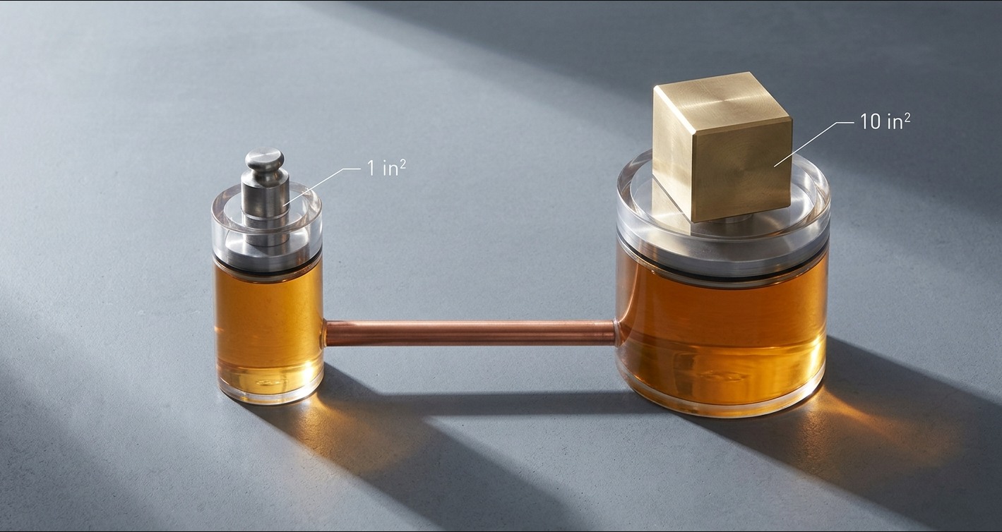
Imagine two pistons connected by a sealed tube of oil. Push down on a small piston with modest force, and the pressure that develops pushes up on a larger piston with proportionally more force.
The trade-off is distance. The big piston moves less than the small one, but the force is multiplied by the ratio of the piston areas. That's the bargain hydraulics offers: trade speed and travel for force.
Quick Reference: Pascal's Law Math
| Input Piston Area | Output Piston Area | Input Force | Output Force | Multiplication |
|---|---|---|---|---|
| 1 in² | 10 in² | 100 lbs | 1,000 lbs | 10x |
| 2 in² | 20 in² | 250 lbs | 2,500 lbs | 10x |
| 1 in² | 50 in² | 100 lbs | 5,000 lbs | 50x |
Why Liquids, Not Gases
Liquids are practically incompressible, so when the pump pushes, the actuator responds almost instantly. Air compresses and stores energy like a spring, which makes pneumatic systems springy and harder to position precisely.
That's why fluid power transmission is the go-to choice when you need stiff, predictable motion under heavy load.
Anatomy of a Hydraulic System: The Six Essential Components
Every system, from a backhoe to an injection molding press, uses the same family of hydraulic system components arranged in a closed loop. Learn these six and you can read any circuit.
The Reservoir (Tank)
The reservoir stores fluid, dissipates heat, and gives air bubbles and contaminants a place to settle out. A common sizing rule is to make the tank capacity two to three times the pump's output in gallons per minute.
The Hydraulic Pump
The pump is the heart of the system, converting mechanical torque from a motor or engine into fluid flow. Gear pumps are cheap and tough, vane pumps are quieter and run at moderate pressure, and piston pumps handle the highest pressures with the best efficiency.
The Hydraulic Cylinder (Actuator)
The hydraulic pump and cylinder pairing is what turns flow back into useful work. Pressurized fluid pushes a piston inside the cylinder, producing linear motion that lifts, clamps, presses, or steers.
Rotary actuators (hydraulic motors) do the same job but produce torque instead of linear force.
Valves: Directional, Pressure, and Flow Control
Three valve families shape the behavior of every circuit. Directional valves choose where the fluid goes, pressure valves cap how hard the system can push, and flow control valves regulate how fast the actuator moves.
Filters and Conditioners
Industry data consistently points to contamination as the cause of roughly 70 to 80 percent of hydraulic failures. Filters belong on the suction side, the pressure line, and the return line, with each location targeting a different particle size and risk.
Hoses, Fittings, and Seals
Hoses fail at the crimp, fittings fail at the threads, and seals fail when fluid chemistry or temperature drifts outside their rated window. Match hose pressure rating to working pressure with at least a 4:1 safety factor, and pick seal materials (Buna-N, Viton, EPDM) based on the fluid you actually run.
Components at a Glance
| Component | Primary Function | Common Failure Mode |
|---|---|---|
| Reservoir | Store and cool fluid | Contamination, aeration |
| Pump | Generate flow | Cavitation, wear |
| Cylinder | Convert pressure to motion | Seal leakage, rod scoring |
| Directional Valve | Control flow path | Spool sticking |
| Relief Valve | Limit max pressure | Setting drift |
| Filter | Remove particulates | Bypass, clogging |
How a Hydraulic Cycle Actually Flows: Step by Step
Energy flows through a hydraulic system in a predictable loop. Tracing it once will make every schematic easier to read.
Step 1: The Prime Mover Drives the Pump
An electric motor or diesel engine delivers rotational torque to the pump shaft. Without this input, nothing else happens.
Step 2: Fluid Is Pulled From the Reservoir
The pump inlet creates a low-pressure zone that draws fluid through a suction strainer. A starved inlet is the number one cause of cavitation, so suction line sizing matters.
Step 3: Pressurization and Flow Distribution
The pump outlet pushes fluid through directional valves toward whichever actuator is selected. A relief valve stands by to dump flow back to tank if pressure climbs above the set limit.
Step 4: Work Is Performed at the Actuator
The cylinder extends or retracts, or a hydraulic motor rotates a load. This is where stored fluid energy becomes mechanical work on the machine.
Step 5: Return and Filtration
Spent fluid flows back through a return filter into the reservoir, where it cools off before being pulled in again. The cycle then repeats, often dozens of times per minute.
Common Hydraulic System Types You'll Encounter
Not all circuits are built the same way. Recognizing the topology in front of you tells you what to expect in efficiency, response, and complexity.
Open-Center vs. Closed-Center Systems
Open-center systems let pump flow circulate freely back to tank when no valve is active. They're simple and cheap but waste energy as heat. Closed-center systems block pump flow at neutral and only release it when an actuator is commanded, which suits multi-function industrial machines better.
Load-Sensing Systems
Load-sensing circuits use a variable-displacement pump that adjusts output to match what the actuators actually demand. The result is significantly less wasted heat and better fuel economy on mobile equipment.
Hydrostatic Drives
A hydrostatic drive pairs a variable pump directly with a hydraulic motor in a closed loop. You'll see this on skid steers, combine harvesters, and CNC feed axes where smooth, infinitely variable speed control is the priority.
| System Type | Best For | Efficiency | Complexity |
|---|---|---|---|
| Open-Center | Simple machinery, fixed pumps | Low–Medium | Low |
| Closed-Center | Multi-actuator industrial | Medium | Medium |
| Load-Sensing | Mobile equipment, excavators | High | High |
| Hydrostatic | Precise speed/torque control | High | High |
Reading a Hydraulic Schematic: A Quick Primer
A schematic is just a wiring diagram for fluid. Once you know the symbol set, the picture tells you exactly how the machine should behave.
Recognizing the Main Symbols
ISO 1219 is the standard you'll see most often. Pumps appear as circles with triangle arrows pointing outward, motors as circles with arrows pointing inward, cylinders as rectangles with a piston rod, and reservoirs as open-topped rectangles or trapezoids.
Tracing the Pressure Path
Start at the pump and follow the line to the first valve. At each valve, look at the active spool position to see which port connects to which. Keep going until you reach the actuator, then follow the return line back to the tank. If the flow path makes sense on paper, the machine should make sense in the field.
Troubleshooting Fundamentals
Most field problems show up as one of a handful of symptoms. A symptom-first approach saves hours of guesswork.
Symptom-Based Diagnostics
| Symptom | Likely Cause | First Check |
|---|---|---|
| Slow actuator speed | Internal leakage, low flow | Pump output, cylinder seals |
| Erratic motion | Air in system | Bleed points, reservoir level |
| Overheating | Restricted flow, undersized cooler | Filters, return line |
| Foaming fluid | Aeration, water contamination | Suction line, fluid sample |
| Pressure spikes | Sticky relief valve | Valve setting, contamination |
When to Take a Fluid Sample
Pull a sample any time performance changes without an obvious mechanical cause, or on a scheduled interval for critical equipment. Lab analysis against ISO 4406 cleanliness codes will tell you particle counts, water content, and wear metals long before a catastrophic failure.
Maintenance Best Practices
Reliability is built, not bolted on. The cheapest hour of maintenance beats the most expensive hour of downtime every time.
Fluid Cleanliness Targets
Aim for ISO 4406 cleanliness of 20/18/15 for general industrial equipment, 18/16/13 for servo systems, and 16/14/11 for high-pressure aerospace and precision applications. Tighter targets mean longer component life.
Scheduled Inspection Checklist
- Daily: Check fluid level, scan for leaks, listen for unusual pump noise.
- Weekly: Inspect filter indicators, verify operating temperature, check hose routing for chafe points.
- Quarterly: Pull a fluid sample, verify relief valve settings, inspect cylinder rods for scoring.
Seal and Hose Replacement Intervals
Manufacturer guidance gives you a starting point, but condition-based replacement is smarter. Hoses showing cover cracks, kinks, or weep stains should come out regardless of age, and seals should be replaced any time a cylinder is opened for service.
Safety Considerations Professionals Should Never Skip
Hydraulic systems store enormous energy, and that energy doesn't disappear when the motor shuts off. Pinhole leaks at 3,000 psi can inject fluid through skin and cause injuries that look minor but require immediate surgical care.
Always follow proper lockout-tagout procedures, relieve pressure at every accumulator before opening a circuit, and never search for a leak with bare hands. A piece of cardboard and safety glasses are the cheapest insurance you'll ever buy.
FAQ: Hydraulics Questions From the Field
What pressure do most industrial hydraulic systems operate at?
Most industrial systems run between 1,500 and 3,000 psi, while mobile equipment often operates from 3,000 to 5,000 psi. High-performance aerospace and press applications can exceed 5,000 psi. Check the relief valve setting and the data plate to confirm your specific machine's rated pressure.
Can I mix different hydraulic fluids?
As a rule, don't. Even fluids with the same viscosity grade can have incompatible additive packages, and mixing them can cause sludge, foaming, or seal swell. If a top-up with the exact same product isn't possible, drain and flush before switching.
How do I know if my pump is failing?
Watch for a high-pitched whine (cavitation), elevated case-drain temperature, falling output flow at rated speed, or metal particles showing up on a fluid sample. Any one of these is a yellow flag, and two together means you should plan a replacement.
What's the difference between hydraulics and pneumatics?
Hydraulics use incompressible fluid and deliver high force with precise positioning, typically at 1,000 to 5,000 psi. Pneumatics use compressed air, are cleaner and faster for light loads, and run at around 80 to 120 psi. Pick hydraulics for force and precision, pneumatics for speed and simplicity.
How often should hydraulic fluid be changed?
Time-based schedules of 2,000 to 4,000 operating hours are common, but condition-based change-out driven by lab analysis almost always wins on cost and reliability. Change immediately if water content, particle count, or oxidation numbers exceed manufacturer limits.
Why is my hydraulic system running hot?
The usual suspects are a clogged or undersized cooler, a sticking relief valve dumping flow back to tank, low fluid level, or internal leakage in a worn pump or cylinder. Start with the simplest checks (fluid level and cooler airflow) before tearing into components.



