

Most hydraulic systems waste energy because the pump runs at full output whether the system needs it or not. A variable piston pump works differently — it adjusts its own flow on the fly, matching output to demand without cycling on and off. Less wasted energy, less heat buildup, longer component life. Getting a handle on how these pumps actually work goes a long way toward designing systems that run cleaner and last longer.
Understanding how swashplate angle, piston stroke, and pressure compensator control interact gives you a clear engineering edge—whether designing new circuits or troubleshooting existing ones. This guide breaks it all down in practical detail.
What Is a Variable Piston Pump?
Definition and Core Function
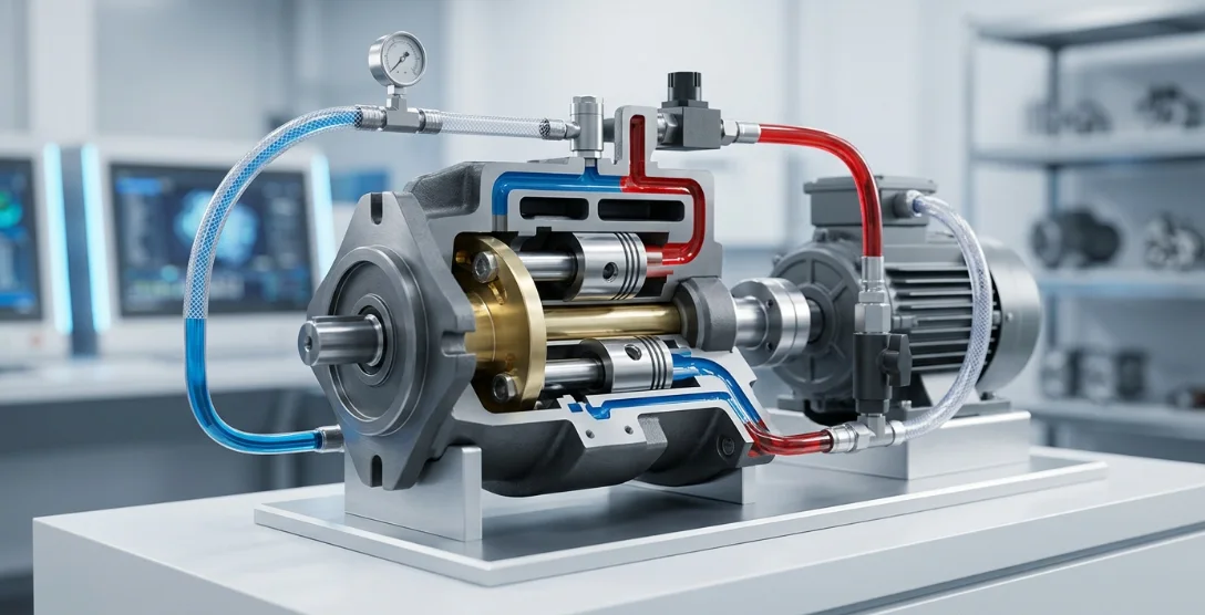
A variable piston pump is a type of variable displacement pump that converts rotational mechanical energy into hydraulic fluid flow. Its defining feature is the ability to change the volume of fluid displaced per revolution without altering shaft speed.
Unlike fixed-displacement designs that deliver constant flow regardless of demand, a variable piston pump modulates output by changing the geometry of its internal stroke mechanism. This makes it the preferred choice wherever energy efficiency and precise flow control matter.
Where Variable Piston Pumps Are Used
These pumps appear across industries that demand high pressure, variable flow, and compact power density. Mobile equipment such as excavators, wheel loaders, and cranes rely on them for responsive, load-sensitive hydraulic systems.
In industrial settings, you'll find them powering injection molding machines, metal forming presses, and machine tool hydraulics. Aerospace flight control actuators and marine steering systems also depend on variable piston pump technology for its reliability and precision.
Key Components of a Variable Piston Pump
Component Breakdown Table
Each part of a variable piston pump serves a specific mechanical or control function. The table below identifies the critical components and their roles within the assembly.
| Component | Function |
|---|---|
| Cylinder Block (Barrel) | Houses pistons and rotates with the drive shaft |
| Pistons | Reciprocate to draw in and push out hydraulic fluid flow |
| Swashplate | Angled plate that controls piston stroke length |
| Valve Plate | Directs fluid between inlet and outlet ports |
| Drive Shaft | Transfers rotational energy from the prime mover |
| Pressure Compensator Control | Adjusts swashplate angle to regulate output pressure |
| Bias Spring | Returns swashplate to maximum displacement position |
| Servo Piston / Control Actuator | Physically tilts the swashplate in response to control signals |
Understanding how these components interact is essential before examining the step-by-step pumping cycle.
How the Pumping Mechanism Works — Step by Step
Rotation and Reciprocation
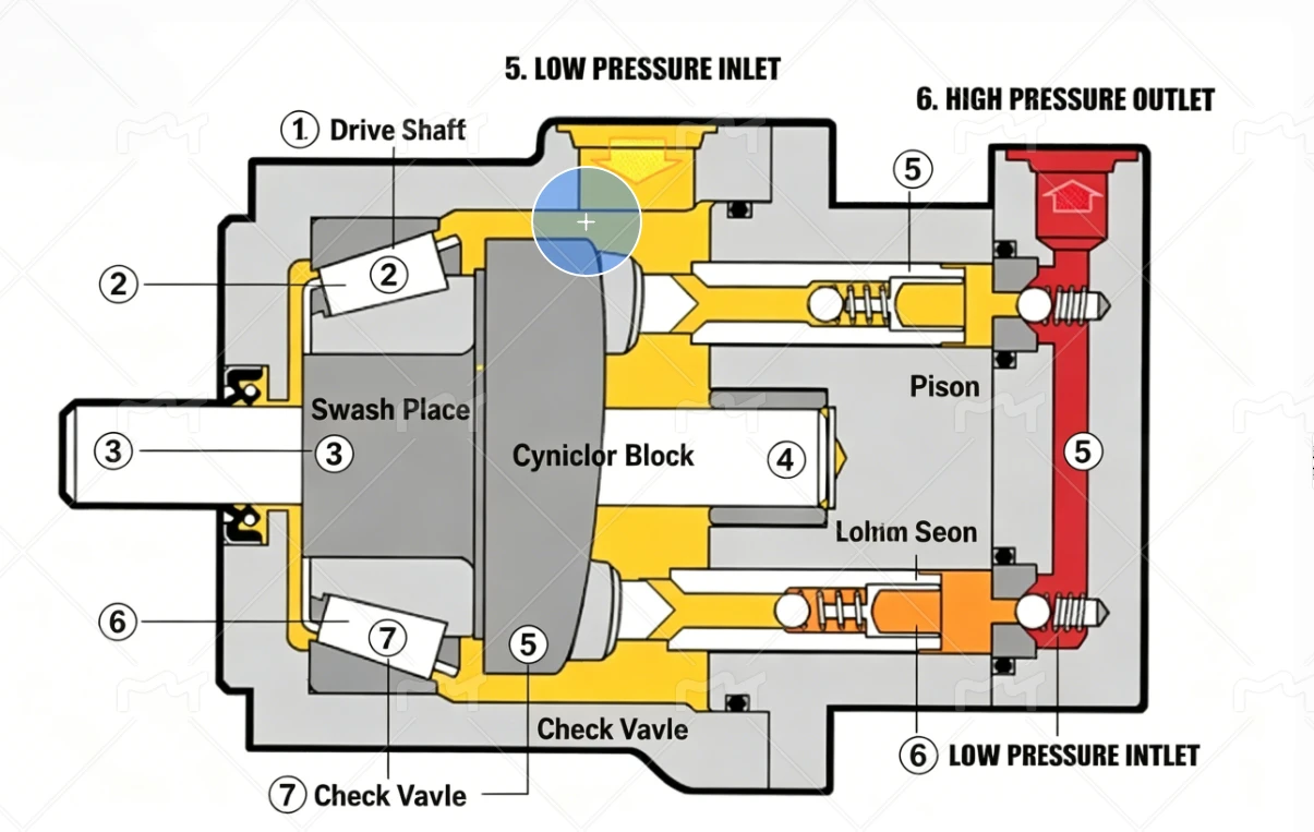
The prime mover — typically an electric motor or diesel engine — spins the drive shaft. The drive shaft is mechanically coupled to the cylinder block, causing it and all seated pistons to rotate together.
As the cylinder block rotates, each piston shoe rides along the angled surface of the swashplate. Because the swashplate is tilted relative to the axis of rotation, pistons are forced to slide in and out of their bores with every revolution. This converts rotary motion into reciprocating linear motion.
Suction Phase
During the half of rotation where a piston retracts away from the valve plate, the expanding volume inside the cylinder bore creates a low-pressure zone. This pressure differential draws hydraulic fluid flow into the bore through the valve plate's inlet kidney port.
The greater the piston stroke length — determined by the swashplate angle — the more fluid enters the bore during this suction phase. Fluid is supplied from the reservoir through the pump's inlet line.
Discharge Phase
As rotation continues, the piston passes over to the high-pressure side of the valve plate. The piston is now pushed inward by the swashplate surface, compressing the trapped fluid and forcing it out through the outlet kidney port.
Because multiple pistons are arranged in a circular pattern (typically seven or nine), suction and discharge events overlap continuously. This produces a smooth, near-constant hydraulic fluid flow at the pump outlet.
How Displacement Is Varied
The Role of Swashplate Angle
The swashplate angle is the single variable that determines how much fluid the pump displaces per revolution. Tilting the swashplate increases the distance each piston travels, directly increasing output volume.
| Swashplate Angle | Piston Stroke Length | Pump Output |
|---|---|---|
| Maximum tilt | Full stroke | Maximum flow |
| Partial tilt | Reduced stroke | Reduced flow |
| Zero (neutral) | No stroke | Zero flow |
This relationship is linear — halving the swashplate angle roughly halves the output flow, giving system designers predictable, proportional control.
Control Methods That Adjust the Swashplate
Several control strategies can position the swashplate, each suited to different application requirements:
- Pressure compensator control — automatically reduces displacement when system pressure reaches a set point, preventing energy waste at idle.
- Load sensing — matches hydraulic fluid flow to actuator demand by referencing the highest load pressure in the circuit.
- Electric proportional — an electronic signal from a controller adjusts swashplate angle precisely for closed-loop automation.
- Manual handwheel — allows an operator to set a fixed displacement position for simple, repeatable applications.
Energy Savings Through Variable Displacement
A fixed-displacement pump running against a relief valve converts excess flow into heat — wasted energy that stresses every component in the circuit. A variable displacement pump eliminates this by producing only the flow the system actually needs at any given moment.
By reducing piston stroke length during low-demand periods, input torque drops proportionally. This lowers electric motor current draw, reduces hydraulic fluid temperature rise, and significantly extends seal and bearing life across the entire system.
Pressure Compensation Explained
How the Pressure Compensator Control Operates
The pressure compensator control is a pilot-operated spool valve that continuously monitors system pressure at the pump outlet. When pressure is below the compensator's set point, the bias spring holds the swashplate at full tilt, delivering maximum flow.
As system pressure rises to the set point, pilot pressure acting on the compensator spool overcomes the bias spring force. The spool shifts, directing control pressure to the servo piston, which physically de-strokes the swashplate.
The result is a self-regulating balance: the pump maintains set pressure with minimal flow output, consuming very little input power while remaining instantly ready to respond when demand returns.
Standby vs. Full-Flow Conditions
| Operating Condition | Compensator State | Swashplate Position | Flow Output |
|---|---|---|---|
| Below set pressure | Inactive | Full tilt | Maximum |
| At set pressure | Active | De-stroked | Near zero (standby leakage only) |
| Pressure drops below set point | Resets | Returns toward full tilt | Increases to meet demand |
This automatic cycling between standby and full-flow conditions is what makes pressure-compensated variable piston pumps so energy-efficient in intermittent-duty applications.
Performance Factors and Specifications
Key Performance Parameters
When selecting a variable piston pump, engineers evaluate several specifications that define its operating envelope and suitability for a given circuit.
| Parameter | Typical Range | Impact |
|---|---|---|
| Operating pressure | Up to 350–420 bar | Determines force capability |
| Displacement | 5–500 cc/rev | Sets maximum flow volume |
| Speed range | 500–3600 RPM | Affects flow rate and noise |
| Volumetric efficiency | 92–97% | Indicates internal leakage losses |
| Overall efficiency | 85–92% | Combined volumetric + mechanical |
Factors Affecting Efficiency
Volumetric and mechanical efficiency are not fixed values — they shift with operating conditions. Fluid viscosity plays a major role: too thin and internal leakage increases; too thick and mechanical drag rises.
Operating temperature directly influences viscosity, creating a linked effect. Swashplate angle also matters — efficiency tends to drop at very low displacement settings where leakage becomes a larger percentage of total flow.
Wear clearances between pistons and bores, valve plate flatness, and system back-pressure all contribute to real-world efficiency losses over the pump's service life.
Advantages and Limitations
Comparison Table
| Advantages | Limitations |
|---|---|
| Energy-efficient — only pumps what is needed | Higher initial cost vs. fixed pumps |
| Reduced heat generation | More complex internal components |
| Longer component life at partial load | Requires cleaner hydraulic fluid |
| Smooth, stepless flow control | Sensitive to contamination |
| Compact power density | Maintenance requires trained technicians |
For most medium- to high-pressure applications with variable duty cycles, the long-term energy savings and reduced component wear justify the higher upfront investment in a variable displacement pump.
Maintenance Best Practices
Routine Inspection Points
Fluid cleanliness is the single most important maintenance factor. Target ISO 4406 cleanliness codes recommended by the pump manufacturer — typically 18/16/13 or better for piston pumps operating above 200 bar.
Monitor case drain flow regularly. A rising case drain volume indicates increasing internal leakage from worn pistons or cylinder block bores. Also verify pressure compensator control adjustment periodically to ensure the set point hasn't drifted.
Inspect the swashplate surface and piston shoes for scoring or uneven wear patterns during scheduled overhauls.
Common Failure Indicators
Increased pump noise — particularly a metallic knocking or whining — often signals cavitation, aeration, or bearing wear. These should be investigated immediately before catastrophic damage occurs.
Sluggish pressure compensator response suggests contamination in the pilot circuit or a weakened bias spring. Loss of piston stroke length control, where the pump fails to reach full displacement, may indicate servo piston seal failure or swashplate pivot wear.
Frequently Asked Questions (FAQ)
What is the difference between a variable and fixed piston pump?
A variable displacement pump changes its output flow by adjusting the swashplate angle, while a fixed pump delivers constant flow regardless of system demand. This means the variable pump can save significant energy during partial-load conditions by reducing piston stroke length automatically.
How does the swashplate angle control flow rate?
Increasing the swashplate angle increases piston stroke length, which displaces more hydraulic fluid per revolution. Decreasing the angle shortens the stroke and reduces output proportionally, giving smooth, stepless flow control without changing shaft speed.
What does a pressure compensator control do?
It automatically reduces pump displacement when system pressure reaches a preset value, preventing energy waste and excess heat during low-demand periods. When pressure drops below the set point, the compensator allows the swashplate to return toward full displacement to meet the new demand.
Can a variable piston pump produce zero flow while still running?
Yes. When the swashplate is at zero angle, pistons do not reciprocate, so no hydraulic fluid flow is generated even though the shaft continues to rotate. The pump remains in standby, consuming minimal power and ready to respond instantly when flow is needed.
Why is fluid cleanliness critical for variable piston pumps?
Tight clearances between pistons, the cylinder block, and the valve plate mean even small contaminant particles can cause scoring, increased leakage, and premature failure. Most manufacturers specify ISO cleanliness levels of 18/16/13 or better to protect these precision-machined surfaces.
What industries rely most on variable piston pumps?
Construction and mobile machinery, aerospace, marine, plastics processing, metal forming, and any application requiring precise, energy-efficient hydraulic fluid flow control. Their ability to match output to demand makes them ideal wherever duty cycles vary significantly.



