A 60:1 pneumatic piston pump fed with 7 bar of shop air will deliver fluid at roughly 420 bar — enough to move chilled wheel-bearing grease through 30 meters of half-inch line without an electric motor anywhere in the circuit. That single ratio explains why, decades after variable-frequency electric drives supposedly made them obsolete, reciprocating air-driven pumps still dominate lubrication rooms, ATEX-classified solvent bays, and adhesive dispensing cells across automotive and heavy-equipment plants.
This guide unpacks the operating principle, component architecture, sizing math, and maintenance framework you need to specify, integrate, and troubleshoot pneumatic piston pumps with confidence.
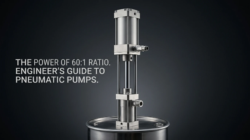
Key Takeaways
- Core principle: Compressed air acts on a large drive piston that reciprocates a smaller fluid piston — output pressure is amplified in proportion to the surface-area ratio.
- Typical ratios: 5:1 for thin oils up to 75:1 for heavy grease and sealants; at 7 bar inlet air, that spans roughly 35–525 bar fluid output.
- Duty sweet spot: Intermittent service, hazardous (ATEX) zones, high-viscosity media, and stall-holding applications.
- Trade-off: Energy efficiency is 10–20% versus 60%+ for electric alternatives — you pay in compressed air for the safety and simplicity.
- MTBF driver: Air quality (FRL condition) is the single largest determinant of air motor life; wet or dirty air is the #1 root cause of premature failure.
Why Pneumatic Piston Pumps Still Dominate Heavy-Duty Fluid Transfer
The Engineering Problem They Solve
Consider a paint mixing room handling xylene-based coatings, or a mine-site lubrication skid dispensing NLGI-2 grease at -10 °C. In both cases, an electric motor is either a code violation or a maintenance liability. A pneumatic piston pump ignores both problems: no ignition source, no thermal overload, and it will simply stop mid-stroke and hold pressure when the downstream valve closes.
Who This Guide Is For
Plant managers, maintenance engineers, and procurement specialists evaluating piston-pump technology for production-line integration, centralized lubrication, or fluid handling upgrades. Working knowledge of pneumatics and hydraulic schematics is assumed.
What You'll Walk Away With
A clear grasp of the reciprocating operating cycle, component-level fault modes, a five-step sizing methodology, and a maintenance framework tied to realistic MTBF targets between 3,000 and 10,000 operating hours.
What Is a Pneumatic Piston Pump?
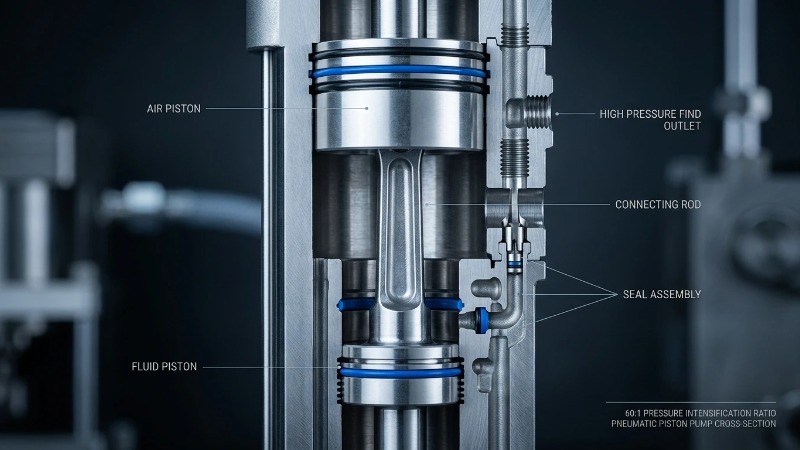
A pneumatic piston pump is a positive-displacement pump that uses compressed air acting on a large drive piston to reciprocate a smaller fluid piston. Output fluid pressure is amplified in proportion to the surface-area ratio between the two pistons, allowing modest shop-air pressures to generate hydraulic-class output.
Positive Displacement vs. Dynamic Pumps
Unlike centrifugal (dynamic) pumps that trade flow for pressure through impeller velocity, positive-displacement pumps deliver a fixed volume per cycle regardless of downstream resistance. That means pressure builds until either the pump stalls, a relief valve opens, or something fails — which is why piston pumps must always be paired with a discharge relief or a stall-tolerant driver.
The Pressure Amplification Principle
Pascal's law tells us that force equals pressure multiplied by area. If the air piston has ten times the area of the fluid piston, the same force is concentrated into one-tenth the area on the fluid side, producing ten times the pressure. A 10:1 pump fed with 7 bar of air therefore delivers approximately 70 bar of fluid pressure — minus friction and cycling losses.
Core Components of a Pneumatic Piston Pump
The Air Motor Section
This is the upper assembly: a large-diameter drive piston, an air distribution valve that alternates supply between the top and bottom chambers, and a pilot mechanism (usually magnetic detents or mechanical trips) that signals end-of-stroke.
The Hydraulic (Fluid) Section
The lower assembly houses the fluid piston, a hardened cylinder sleeve, and the primary packing seals. Seal material choice — PTFE for aggressive solvents, Viton for hot oils, UHMWPE for abrasive slurries — dictates chemical compatibility and service life more than any other single spec.
Check Valves and Foot Valve
Inlet and outlet ball or poppet checks enforce one-directional flow during each stroke. The foot valve at the suction inlet is often the first component to foul in dirty-media service and is the usual suspect when a primed pump suddenly loses output.
Reversing Mechanism
A shuttle valve or spool switches air between chambers at each end-of-stroke, driven by pilot pressure from a trip mechanism. Icing here — caused by air expansion combined with humid supply air — is the classic cause of mid-stroke stalls.
Component Reference Table
| Component | Function | Common Materials | Typical Failure Mode |
|---|---|---|---|
| Air motor piston | Drives reciprocation | Anodized aluminum | O-ring wear, scoring |
| Fluid piston | Displaces process media | 316 SS, ceramic-coated | Seal blow-by |
| Check valves | One-way flow control | SS/carbide balls, PEEK seats | Debris fouling, chatter |
| Air distribution valve | Cycles air flow | Brass, polymer spools | Icing, contamination |
| Packings/seals | Chamber isolation | PTFE, Viton, UHMWPE | Chemical swelling, extrusion |
How Pneumatic Piston Pumps Work: The Operating Cycle Step-by-Step
Stage 1: Downstroke — Air Enters the Upper Chamber
Compressed air is routed above the drive piston, pushing it downward. On the fluid side, the lower inlet check opens and process media is drawn into the cylinder, while the upper discharge check is held closed by line pressure above it.
Stage 2: End-of-Stroke Signal
As the piston reaches the bottom of travel, a mechanical trip or magnetic detent shifts the pilot valve. That pilot signal drives the main air distribution spool from one position to the other.
Stage 3: Upstroke — Fluid Discharge
Air is now supplied below the piston, and the upper chamber vents to atmosphere. The lower inlet check slams closed, the upper discharge check opens, and fluid is expelled under the amplified pressure defined by the pump ratio.
Stage 4: Cycle Reset
The cycle repeats at a rate determined by downstream demand — typically 20–60 cycles per minute under working load. When the discharge line reaches setpoint (a closed dispense valve, for example), backpressure balances the drive force and the pump stalls harmlessly, holding pressure indefinitely.
Single-Acting vs. Double-Acting Configurations
Single-acting pumps discharge fluid on only one stroke, producing pronounced pulsation and lower average flow. Double-acting designs discharge on both up and down strokes, halving pulsation amplitude and roughly doubling flow at the same cycle rate — the standard choice for continuous dispensing or transfer.
Understanding Pressure Ratios and Performance Curves
Reading a Ratio Spec
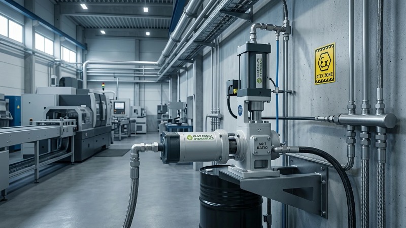
A pump labeled 30:1 will output 30 bar of fluid pressure for every 1 bar of air supply, at stall (zero flow). Real-world working pressure at cycling is always lower because of friction, seal drag, and cycling losses — expect 85–92% of the theoretical value.
Flow vs. Pressure Trade-off
Pneumatic piston pump performance curves slope downward: as backpressure rises, cycle rate slows because more air pressure is needed to overcome fluid resistance per stroke. Always specify at the working point, not the stall point.
Typical Output Ranges by Ratio
| Pump Ratio | Air Input (bar) | Fluid Output at Stall (bar) | Typical Application |
|---|---|---|---|
| 5:1 | 7 | 35 | Light oil transfer, low-viscosity dispensing |
| 10:1 | 7 | 70 | Grease, hydraulic fluid transfer |
| 30:1 | 7 | 210 | High-viscosity lubricants, sealants |
| 60:1 | 7 | 420 | Heavy grease, asphalt, adhesives |
| 75:1 | 7 | 525 | Specialty high-pressure injection |
Application Scenarios in Industrial Machinery
Lubrication Systems for CNC and Assembly Lines
Centralized progressive or dual-line lubrication skids commonly use 30:1 or 50:1 grease pumps to feed dozens of lube points across a production cell. The stall-and-hold behavior is ideal: the pump refills the header, stalls, and only cycles again when a metering valve fires.
Chemical and Solvent Transfer
ATEX Zone 1 and Zone 2 areas — paint kitchens, adhesive rooms, solvent recovery — routinely prohibit electric motors without expensive Ex-rated enclosures. A pneumatic piston pump is intrinsically safe by design, needing only bonded piping and a grounded fluid path.
Paint, Adhesive, and Sealant Dispensing
Consistent stall pressure translates directly into consistent bead width and spray fan geometry. Double-acting designs with integrated surge suppressors are standard for automated spray booths.
Integration with Hydraulic Power Units
Pneumatic piston pumps often complement gear pumps and cycloidal motors in hybrid power systems — for example, charging a pilot-circuit accumulator during machine idle time while a main HGP or CBK-series gear pump handles the working circuit. Directional control valves and relief valves in the shared circuit isolate the two pressure sources.
Pneumatic Piston Pumps vs. Alternatives: Pros & Cons
| Advantages | Limitations |
|---|---|
| Intrinsically safe — no electrical ignition risk | Energy efficiency of 10–20% versus 60%+ for electric |
| Stalls under backpressure without damage or overheating | Requires clean, dry compressed air — FRL is non-negotiable |
| Infinite speed control via a single air regulator | Pulsation often requires dampeners downstream |
| Handles abrasive and high-viscosity media well | Noise levels of 75–85 dB(A) at full cycle rate |
| Low upfront cost and simple mechanical repair | Air motor icing in humid environments without a dryer |
Head-to-Head Comparison
| Criterion | Pneumatic Piston | Electric Gear Pump | Hydraulic-Driven Piston |
|---|---|---|---|
| Energy efficiency | Low–Medium | High | Medium |
| Safety in ATEX zones | Excellent | Requires certified motor | Good |
| Stall behavior | Safe, holds pressure | Overheats or trips | Relief valve required |
| Max pressure | Up to ~500+ bar | Moderate | Very high |
| Maintenance interval | 2,000–5,000 hrs | 5,000–10,000 hrs | 3,000–6,000 hrs |
| Upfront cost | Low–Medium | Medium | High |
Sizing and Specification: A Procurement Framework
Step 1: Define Fluid Properties
Nail down viscosity in centipoise at operating temperature (not at 20 °C — cold grease can be an order of magnitude thicker), specific gravity, abrasiveness, and full chemical compatibility with elastomers and wetted metals.
Step 2: Calculate Required Flow and Pressure at Point of Use
Add line losses, elevation head, and dispense-valve pressure drop to the delivery-point requirement. A 30-meter run of ¾-inch line handling NLGI-2 grease can easily add 40–80 bar of pressure loss on its own.
Step 3: Match Ratio to Available Air Supply
Choose the ratio so that working fluid pressure is delivered at 60–80% of maximum air supply, leaving headroom. Then verify compressor SCFM output exceeds peak pump demand by at least 20–30%.
Step 4: Verify Duty Cycle and MTBF Expectations
Continuous 24/7 operation versus intermittent dispensing dramatically shifts realistic seal life. A pump rated for 30% duty cycle running continuously will see MTBF cut in half or worse.
Step 5: Confirm Standards Compliance
Verify ISO 9001 manufacturing traceability, CE marking for the EU market, and ATEX category (typically II 2G for Zone 1) where the installation demands it. Ask for the certificate — a claim on a datasheet is not proof.
Total Cost of Ownership Considerations
Air Consumption Costs
A useful rule of thumb: delivering the same hydraulic energy pneumatically costs roughly 4–8× more in electricity at the compressor than a direct electric-driven pump would consume. For low-duty applications this is trivial; for continuous transfer, it dominates the TCO calculation.
Maintenance and Spare Parts
Annualized cost is driven by seal-kit replacement, check-valve rebuilds, and periodic air-motor overhauls. Modular designs with standardized, OEM-compatible components dramatically reduce mean time to repair.
Downtime and MTBF Impact
The true cost is rarely the part — it's the line being down. Stocking a service kit for each critical pump typically pays back the first time you avoid a two-shift shutdown waiting on a courier.
ROI Scenarios
Pneumatic wins on intermittent duty, hazardous zones, high-viscosity media, and applications where stall-and-hold behavior replaces a control loop. It loses on 24/7 high-flow water-like duty in safe environments, where an electric centrifugal or gear pump will pay back its higher upfront cost in months.
Installation and Integration Best Practices
Air Preparation: FRL Units
Filter–regulator–lubricator sizing is not optional. The single most common cause of premature air-motor failure is contaminated or wet inlet air. Specify 5-micron filtration minimum, a regulator sized for peak SCFM without pressure droop, and a lubricator dosed for the pump's cycle rate.
Mounting and Vibration Isolation
Rigid mounts transmit pulsation into the surrounding structure and piping. Elastomeric isolators or a dedicated skid frame with flexible piping connections extend the life of downstream instruments significantly.
Pulsation Dampeners and Surge Suppression
Add a bladder-type dampener within 10 pipe diameters of the discharge port on any application feeding a coating gun, meter, or precision dispenser. Size the pre-charge to about 60–80% of working line pressure.
Suction-Side Considerations
With viscous media, always design for flooded suction if possible. Suction lift with cold grease is a reliable recipe for cavitation, seal wear, and phantom "loss of prime" callouts.
Common Failure Modes and Troubleshooting
Pump Stalls Mid-Stroke
Usually icing in the air motor, a contaminated distribution valve, or air supply that droops under peak demand. Check FRL bowl condition, verify supply pressure while the pump is cycling, and warm the air motor to diagnose ice.
Erratic Cycling or No Output
A failed inlet or outlet check, worn fluid seals allowing bypass, or an air leak past the drive piston. Isolate by capping the discharge and watching the cycle — a pump that cycles freely with the discharge blocked has failed fluid seals.
Excessive Air Consumption
Almost always bypass across worn fluid packings; the pump cycles more per unit of delivered fluid, burning air.
Pulsation and Line Hammer
Undersized or missing dampener, or check-valve chatter from a resonant suction line. Add or repressurize the dampener first.
Troubleshooting Quick-Reference Table
| Symptom | Likely Cause | First Action |
|---|---|---|
| Won't start | Low air pressure at inlet | Verify FRL regulator setpoint under load |
| Runs but no fluid | Foot valve stuck or lost prime | Inspect suction check and re-prime |
| Cycles without load | Fluid seal bypass | Rebuild fluid section |
| Ices up on air motor | Wet air, high cycle rate | Add refrigerated dryer, upsize air line |
| Loud knocking | Cavitation or worn checks | Reduce suction lift; inspect check seats |
Maintenance Schedule and MTBF Planning
Daily / Weekly Checks
Drain the FRL filter bowl, verify supply pressure under running load, and walk the pump for visible air or fluid leaks. This five-minute routine catches the majority of failures before they become downtime events.
Quarterly Service
Top up or verify the lubricator, check external fastener torque (vibration walks fasteners loose over thousands of cycles), and inspect suction strainers.
Annual Overhaul
Full seal-kit replacement, check-valve inspection and rebuild, and air-distribution-valve service. Budget one full overhaul per year for continuous-duty pumps, every two to three years for intermittent-duty units.
Predictive Maintenance Integration
Simple cycle counters and inline pressure transducers feeding a plant CMMS platform turn a reactive maintenance program into a predictive one. Trending cycle count against delivered volume exposes seal bypass long before it becomes a visible leak.
Common Mistakes to Avoid
Undersizing the Air Supply
Compressor SCFM capacity must exceed peak pump demand by 20–30%, measured at the pump inlet under working conditions — not at the compressor discharge. Long runs of undersized air line silently starve the pump.
Ignoring Fluid Compatibility Charts
The wrong elastomer choice kills seals within weeks. Cross-reference every wetted material — including the check-ball seats — against the actual media, additives, and cleaning solvents used in flush cycles.
Running Continuous Duty on Intermittent-Rated Pumps
A pump rated for 30% duty cycle pushed to 100% will typically see MTBF cut by half or more. Spec the duty rating against realistic worst-case demand, not average demand.
Skipping the FRL
A false economy. The savings on a filter–regulator–lubricator are erased the first time you rebuild an iced-up air motor, and the failure will always happen mid-shift.
Neglecting Discharge Pulsation
Pulsation damages downstream flow meters, pressure transducers, and threaded fittings. Add a dampener during commissioning; retrofitting one after instruments have been shaken loose is a much larger job.
Frequently Asked Questions
What is the typical service life of a pneumatic piston pump?
Expect 3,000–10,000 operating hours between major overhauls, depending on duty cycle, media abrasiveness, and air quality. Clean-air, intermittent-duty pumps handling lubricating oils routinely exceed 10,000 hours; abrasive slurry service can be under 3,000.
Can a pneumatic piston pump run dry?
Yes, generally without damage — a significant advantage over centrifugal designs that rely on the fluid for cooling and bearing lubrication. Extended dry running can eventually accelerate seal wear, but a lost-prime event will not destroy the pump the way it would a centrifugal.
How much compressed air does a pneumatic piston pump consume?
Air consumption is roughly proportional to cycle rate and drive-piston displacement. A mid-size 30:1 grease pump cycling at 40 strokes/min typically draws in the range of 15–30 SCFM at 7 bar; consult the manufacturer curve for the specific working point.
What's the difference between a piston pump and a diaphragm pump?
Piston pumps achieve much higher pressure (up to 500+ bar versus roughly 8 bar for standard AODD diaphragm pumps) and handle high-viscosity media better. Diaphragm pumps are simpler, self-priming to greater suction lifts, and better for shear-sensitive or particulate-laden fluids at moderate pressure.
Are pneumatic piston pumps ATEX certified?
Many are — look for the marking on the nameplate, typically in the format II 2G for Zone 1 gas atmospheres. Certification requires specific materials, grounded construction, and documented spark-free operation; a pump being "air-driven" does not automatically make it ATEX compliant.
Can they handle abrasive slurries?
Yes, with the right specification: ceramic-coated or hardened stainless fluid pistons, tungsten-carbide check balls and seats, and UHMWPE packings extend service life dramatically in abrasive service. Standard SS trim will wear rapidly.
How do I integrate a pneumatic piston pump with an existing hydraulic power unit?
Treat the pneumatic pump as a secondary pressure source feeding through a check valve into the shared circuit — typically at a pilot manifold, an accumulator charge port, or a low-flow auxiliary line. Coordinate with the main gear pump discharge through directional control valves, and always place a relief valve on the pneumatic branch sized below the weakest downstream component's rating.
Conclusion and Next Steps
Recap: When Pneumatic Piston Pumps Are the Right Choice
The sweet spot is unmistakable: hazardous-area installations, high-viscosity media, intermittent duty cycles, and applications that benefit from inherent stall-and-hold behavior. Outside that envelope, an electric-driven gear or centrifugal pump will usually offer a better lifetime cost.
Specification Checklist Before You Buy
- Fluid: Viscosity at operating temperature, chemical compatibility, abrasiveness.
- Flow: Peak and average demand at the point of use, including line losses.
- Pressure: Working pressure at delivery, plus elevation and dispense-valve drop.
- Air supply: Available SCFM and pressure at the pump inlet under load.
- Environment: Ambient temperature, humidity, ATEX zone classification.
- Certification: ISO 9001, CE, ATEX category as required by the installation.
Talk to Olive Branch Hydraulics
If you're specifying a new pneumatic piston pump or integrating one into a hybrid circuit alongside gear pumps, directional valves, or relief valves, we can help you shortcut the sizing work. Every unit we ship is built under ISO 9001 with 100% pre-shipment testing on calibrated pressure benches and flow meters — no exceptions.
Next actions:
- Request a compatibility assessment — send your fluid, flow, pressure, and environment specs and we'll return a matched pump ratio and seal package.
- Request a factory-direct quote on OEM-compatible piston pumps, HGP/K3V/CBK gear pumps, BM/BMR cycloidal motors, or multi-way and directional valves with SAE-standard P/T port configurations.
- Consult on hybrid system integration — pneumatic piston pumps paired with our gear pump and valve range for pilot circuits, accumulator charging, and centralized lubrication skids.
Send your specification sheet or existing pump nameplate and we'll respond with a drop-in-compatible proposal, backed by our full testing documentation.