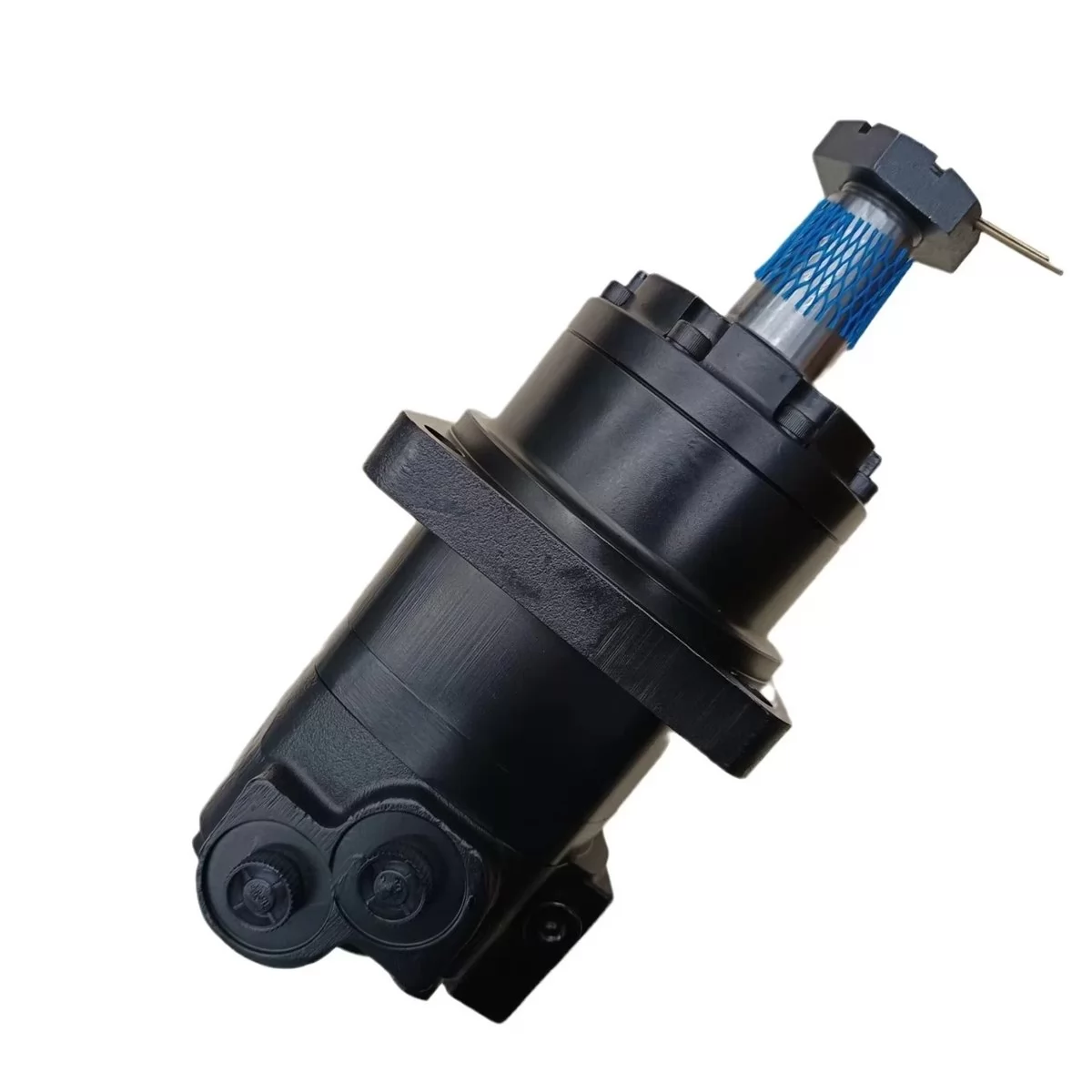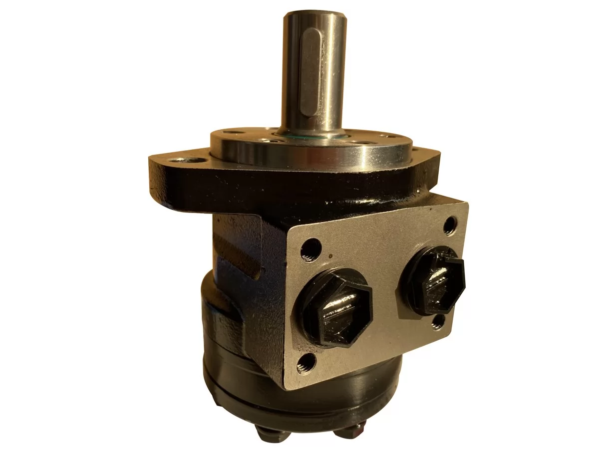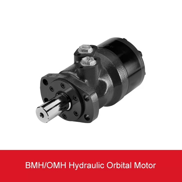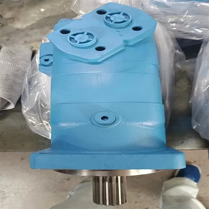

A replacement motor can have the same displacement on the nameplate as the old unit and still fail within weeks once it runs above its rated speed. A high speed hydraulic motor is a hydraulic motor designed to turn at high shaft speed with modest torque per revolution. This guide covers how to select one, how to compare designs and how to source an accurate replacement.
Fast-running hydraulic motors suit drives that can use a reduction gearbox or that need high shaft speed directly, such as travel drives, fans, winches and pump drives. Most are axial piston units, and bent axis designs handle the most demanding duties. Speed alone does not get you a correct match. Use pressure, duty cycle and the complete type code as well.
What Are Fast-Running Hydraulic Motors Used For?
Fast-running hydraulic motors drive loads that need high shaft speed and moderate torque, often through a reduction gearbox that multiplies torque at the output. Most are axial piston designs. Gear and vane motors cover lighter, lower-cost duties where efficiency and service life matter less.
Speed, Displacement and Torque in Plain Terms
Displacement is the volume of fluid a motor takes in per shaft revolution, usually given in cc/rev. Output torque scales with displacement multiplied by the pressure difference across the motor. Shaft speed scales with flow divided by displacement.
So a small motor fed with a given flow turns fast and produces less torque per revolution. A large motor fed with the same flow turns slowly with more torque. If you put a reduction gearbox after a small, fast motor, you get high output torque at low speed, and the package is often lighter and more efficient than a large slow motor driving the load directly.
The trade-off is mechanical. A gearbox adds parts, oil and a service point. It also changes how the motor sees overrunning loads, because the gearbox ratio multiplies any backdriving speed at the motor shaft.
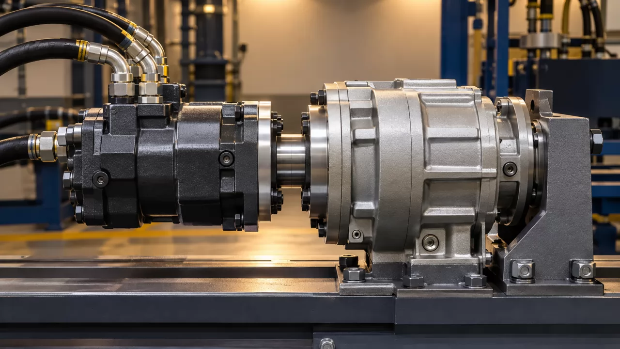
Typical Duties in Mobile and Industrial Machinery
- Travel drives: Walking motors on excavators, road rollers, pavers and drills, usually paired with a planetary reduction gearbox.
- Swing drives: Excavator slewing, where the motor runs through a gearbox and a brake.
- Fan drives: Cooling fans on mobile and stationary equipment, where speed control reduces power loss.
- Winches and conveyors: Drum and belt drives in mining, metallurgy and plant equipment, typically geared.
- Auxiliary drives: Motors that drive a secondary pump, mixer or generator on construction and plant machinery, including concrete mixer trucks.
High Speed Hydraulic Motor vs Low Speed High Torque Motor: Which Does Your Machine Need?
Choose a high-speed motor for compact, efficient drives that run through a gearbox, or that need shaft speed directly. Choose a low speed high torque (LSHT) motor for direct-drive wheels, augers and slow, heavy loads where a gearbox would add cost or space. The decision depends on duty cycle, installation envelope and efficiency targets.
An LSHT motor is a hydraulic motor built to deliver high torque at low shaft speed without a gearbox. Orbital (gerotor or geroler) motors such as the OMS, OMT and BM series are the most common type. An axial piston motor is a hydraulic motor in which pistons arranged parallel to the shaft axis convert fluid pressure into rotation. Examples include the A2FM and A6VM.
Comparison Table: Design, Speed Band, Torque, Gearbox Need, Efficiency, Cost Drivers
| Attribute | Bent axis fixed (A2FM) | Bent axis variable (A6VM) | Orbital LSHT (OMS, OMT, BM series) |
|---|---|---|---|
| Typical speed band | High; often several thousand rpm in smaller sizes, lower as size increases | High; maximum speed usually reached at reduced displacement | Low; usually up to several hundred rpm depending on displacement |
| Torque per revolution | Lower; multiplied by a gearbox | Adjustable with displacement | Higher; suited to direct drive |
| Gearbox need | Usually required for slow loads | Usually required for slow loads | Often not required |
| Efficiency | Higher across a wide speed range | Higher; can be optimised by displacement control | Lower, especially at high pressure and low speed |
| Cost drivers | Size, shaft and flange options, seals | Control type, sensors, regulator settings | Displacement, shaft type, mounting, brake options |
The table comes down to one point: piston motors win on efficiency and power density, and orbital motors win on simplicity wherever slow, direct-drive torque is the actual requirement.
Orbital displacements give a sense of scale. For example, the B6K series covers 195-985 cc/rev and the BM4 series covers 245-800 cc/rev. These figures are far larger per revolution than most piston motors used in geared drives.
Why Do Bent Axis Piston Designs Dominate Fast-Turning Drives?
Bent axis piston motors dominate demanding fast-turning drives because the angled cylinder block gives high power density, good starting torque and high volumetric efficiency at speed. That combination makes the bent axis hydraulic motor the usual choice for mobile travel, swing and winch drives running under heavy, variable loads.
Bent Axis Piston Motor for High Speed Applications: Where the Geometry Helps
A bent axis motor is an axial piston motor whose cylinder block sits at an angle to the drive shaft. The pistons connect to the shaft flange through ball joints. Piston force goes almost directly into shaft torque, and the pistons carry little side load in their bores.
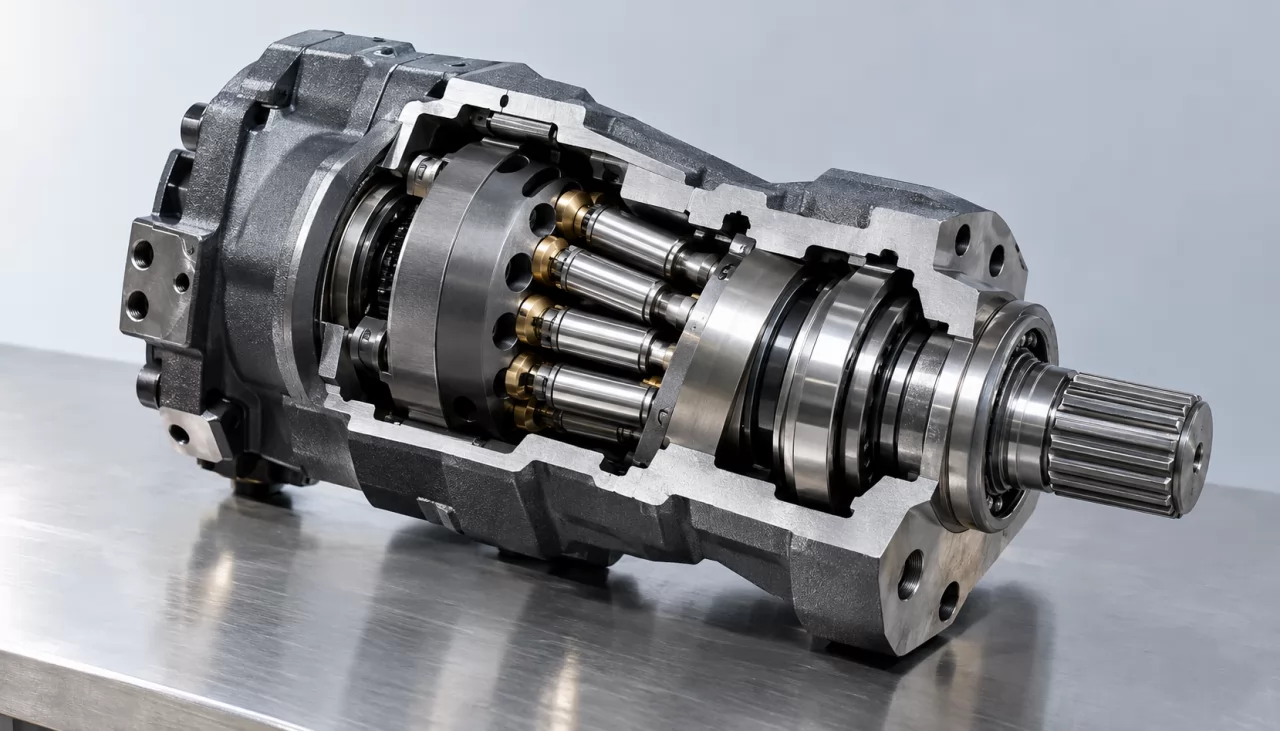
A swashplate motor works differently. The cylinder block runs in line with the shaft, and the pistons push against an inclined plate through sliding slippers. Slipper sliding speed and piston side loads limit how fast the unit can run. For a similar displacement, bent axis units therefore usually tolerate higher speeds and give better starting torque.
The penalty is size and shape. A bent axis housing is longer and bulkier than an in-line swashplate unit. The shaft bearings also carry the full piston reaction loads, so bearing life depends heavily on pressure and speed. Swashplate motors remain common where a compact in-line envelope matters more.
Fixed vs Variable Displacement: A2FM/A2FE and A6VM/A6VE
- A2FM fixed displacement motor: One displacement and no regulator. It is simpler and cheaper, and output speed changes only with flow.
- A6VM variable displacement motor: Displacement is adjusted by a control (hydraulic, electric proportional or two-position). Lower displacement gives higher speed and higher displacement gives more torque, which widens the usable speed range of a travel drive.
- Plug-in versions (A2FE, A6VE): These have a housing designed to sit inside a gearbox or drive housing. They shorten the overall package and suit gearbox-integrated track drives and winches.
A variable motor brings regulator setup, extra control lines and more points of mismatch. Only specify one if the machine actually needs the extra speed range.
Gear and Vane Motors as Budget Alternatives
Gear and vane motors cost less and tolerate simple installations. They are acceptable for light, intermittent duty such as small fans, agitators and auxiliary drives. Their efficiency is typically lower than piston motors, internal leakage grows as parts wear, and service life under continuous high pressure is shorter. Do not use them where precise speed holding or heavy continuous duty is required.
How to Choose a High Speed Hydraulic Motor for a Pump Drive or Travel Drive
Choosing a fast-running motor starts at the load. Define the required output speed and torque, account for any gearbox ratio, and work back to motor displacement and working pressure. Then confirm control type, mounting, shaft and porting against the existing machine before you approve a sample.
Selection Criteria Checklist
- Pressure ratings: Check rated continuous pressure and peak pressure against the system relief setting. Peak spikes during braking or reversing often exceed nominal working pressure.
- Speed limits: Distinguish maximum continuous speed from intermittent maximum speed. Variable motors often allow higher speed only at reduced displacement.
- Displacement and control: Match displacement to the flow available from the pump. For variable units, specify the control (hydraulic, electric proportional, two-position), its start and end settings, and the control voltage if electric.
- Mechanical interface: Confirm the flange standard (SAE, ISO or DIN), the shaft type (spline standard, keyed or tapered), the port type and position, and the direction of rotation.
- Case drain, flushing and fluid: Confirm the case drain port size and routing, whether a flushing valve is needed in closed circuits, the required viscosity range and the filtration level. The cleanliness target is usually stated as an ISO 4406 code.
- Duty cycle: Record the time spent at high speed and high pressure, the ambient temperature and the start-stop frequency. These drive bearing life more than any single rating does.
Rule of thumb: if the motor will spend most of its working hours near any one maximum rating, move up a size or change the gearbox ratio.
Tip: Size for the duty cycle, not the peak. Long periods near maximum speed or pressure shorten bearing life sharply. Leave margin for overrunning loads, such as a machine travelling downhill or a winch lowering a load, and for loads that arrive faster than the original design assumed.
Axial Piston Hydraulic Motor Replacement: What Information Gets an Accurate Match?
An accurate axial piston hydraulic motor replacement starts with three details: the original product code, the machine model and the equipment details. Brand names and model numbers are used only to identify the replacement. Compatibility depends on the complete assembly code, not the series name or displacement alone.
Reading the Type Code on the Nameplate
A type code is the full alphanumeric designation on the nameplate that defines every configurable feature of the motor. Most axial piston motor codes are laid out in roughly the same order:
- Product family and series, for example A2FM or A6VM, followed by a series number.
- Nominal size, which normally matches the displacement in cc/rev.
- Control device and its settings (variable motors only).
- Direction of rotation or bidirectional operation.
- Seal material.
- Shaft end and spline standard.
- Mounting flange.
- Port type and position, plus any integrated valves.
- Sensor and accessory options.
Mismatches most often come from the shaft, the port position and the control settings. A worn or painted nameplate makes these the hardest characters to read. Clear photos of the nameplate, shaft end and port face cut down the back-and-forth.
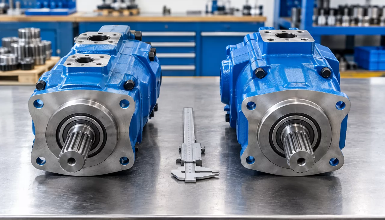
If the nameplate is missing, the machine model and serial number, together with measurements of the shaft, flange and ports, can usually narrow the options. A sample check is still advisable.
Note: Interchangeable is not the same as identical. Before approving a sample, check the shaft spline, the port orientation, the control settings and the speed-sensor provisions. A motor that bolts on but has a different regulator start pressure or no sensor port can disrupt machine behaviour or trigger controller faults.
What QC, Documentation and Logistics Should You Agree Before Ordering?
Agree the inspection scope and required documents in writing in the quotation before ordering a replacement motor. With Olive Branch Hydraulics, quality checks (dimensional checks, leak inspection, and pressure/flow testing where applicable) and documents are agreed in the quotation. Every unit goes through 100% final inspection before packaging.
Order Flow and Shipment Steps
- Inquiry with model, quantity and destination port.
- Design drafts and 3D renders for approval.
- Sampling.
- Production with in-process quality control.
- 100% final inspection.
- Packaging and global shipping.
Olive Branch Hydraulics is the brand of Xinji Olive Branch Trading Co., Ltd., a trading company founded in July 2023. Its manufacturing partner in Ningjin was established in August 2010, and the production site is about 9 km from the Xinji sales office. Any third-party document references belong to their holders and are not Olive Branch Hydraulics certifications. Confirm which documents your market requires before the quotation is finalised.
Common Pitfalls After Installation
- Case drain problems: Undersized, kinked or blocked drain lines raise case pressure, which can damage shaft seals and overheat the unit.
- Overspeed: Overrunning loads without adequate counterbalance or brake valving can push the motor past its speed limit.
- Cavitation: Low boost or charge pressure starves the motor on its inlet side and erodes internal surfaces.
- Dirty commissioning: Contaminated fluid during first start-up, often from new hoses or an unflushed circuit, causes early wear. Flush and fill the case before start-up.
FAQ
Can an A2FM directly replace an orbital motor on the same machine?
Usually not. An A2FM runs at much higher speed with lower torque per revolution, so it typically needs a reduction gearbox along with different mounting, porting and case drain arrangements.
Why do fast-running piston motors fail early in the field?
The most common causes are contamination, overspeed, cavitation and excessive case pressure. Bearing fatigue from long periods near maximum ratings comes next, so check the duty cycle and the drain routing along with the motor itself.
Is a separate case drain line always required?
For axial piston motors, it nearly always is. The case drain should return to the tank with low back pressure. Some gear and orbital motors drain internally, but check the specific model's requirements.
What details get the fastest quote for a replacement motor?
Send the original product code, the machine model, the quantity and the destination port. Nameplate and shaft photos help resolve unclear codes before the sampling stage.
Request a Matched Replacement or Quote
To get a quote, send the model, quantity and destination port to [email protected] or +8615075996564. For replacements, include the original product code and machine model. Replies come within 24 hours.