

A hydraulic directional control valve is the decision-maker in any fluid power system. It determines where pressurized oil goes, when it gets there, and how it returns to the reservoir. Understanding hydraulic spool valve operation is essential for anyone designing, maintaining, or troubleshooting hydraulic circuits.
This guide walks through the internal mechanics, valve actuation methods, classification systems, and real-world applications of directional control valves. Whether you work with mobile equipment or industrial presses, the principles of directional flow control covered here apply across the board.
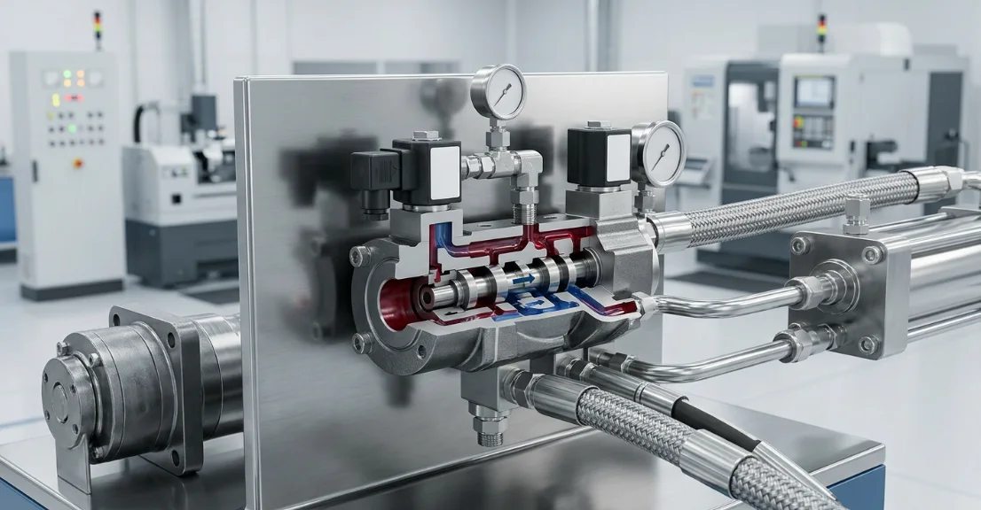
What Is a Hydraulic Directional Control Valve?
A hydraulic directional control valve is a mechanical device that controls hydraulic fluid path routing within a circuit. Its primary job is to direct pressurized fluid from the pump to specific actuators — cylinders or motors — and then route the return fluid back to the tank.
Without this valve, a hydraulic system would have no way to control the direction of actuator movement. It acts as a traffic controller, opening and closing internal passages to achieve precise hydraulic circuit switching on demand.
These valves range from simple two-port on/off devices to complex multi-port, multi-position configurations capable of managing sophisticated motion sequences. The specific design depends on the system's pressure, flow rate, and control requirements.
Core Components of a Directional Control Valve
Every directional control valve shares a common internal anatomy. Understanding these components is the foundation for grasping how hydraulic spool valve operation achieves directional flow control.
The spool is the central moving element. It slides within a precision-machined bore inside the valve body, and its position determines which ports are connected or blocked at any given moment.
| Component | Function |
|---|---|
| Valve Body (Housing) | Contains internal passages and port connections |
| Spool | Slides within the bore to open/close flow paths |
| Lands | Raised sections on the spool that block or allow flow |
| Ports (P, T, A, B) | Entry/exit points for pressure, tank, and work lines |
| Springs | Return spool to neutral/center position |
| Seals / O-Rings | Prevent internal and external leakage |
The valve body is typically cast iron or machined steel, designed to withstand system pressures that can exceed 5,000 PSI. Internal passages are drilled or cast to connect each port to specific zones within the spool bore.
Lands on the spool are the raised cylindrical sections that create a seal against the bore wall. The annular grooves between lands form the channels through which fluid flows when the spool is shifted to the correct position.
How Hydraulic Spool Valve Operation Works
Hydraulic spool valve operation is based on a simple principle: a cylindrical spool moves linearly within a close-tolerance bore, aligning or blocking internal passages to route fluid. The spool position directly determines which ports communicate with each other.
When an actuation force is applied, the spool shifts against spring resistance. This movement aligns the grooves between the spool lands with specific port passages in the valve body, creating a continuous fluid path from pump to actuator and from actuator back to tank.
The precision fit between spool and bore — typically 2 to 5 microns of clearance — minimizes internal leakage while still allowing smooth, low-friction movement. This tight tolerance is why fluid cleanliness is critical to reliable operation.
Neutral Position (Center Condition)
When no actuation force is applied, the springs hold the spool in its center or neutral position. What happens to the fluid in this state depends entirely on the center spool configuration selected for the application.
In a closed-center design, all ports are blocked. The pump flow has nowhere to go, so system pressure rises to the relief valve setting. The actuator remains locked in position because both work ports are sealed.
In an open-center design, all ports are interconnected. Pump flow passes freely through the valve to tank at minimal pressure, unloading the pump. The actuator is free to drift because its ports connect to tank. A tandem-center configuration offers a middle ground — pump flow returns to tank (unloading the pump) while the work ports remain blocked (locking the actuator).
Shifted Position (Actuator Extend / Retract)
When the spool shifts to one side, it connects the pressure port (P) to one work port while simultaneously connecting the opposite work port to the tank port (T). This is the fundamental mechanism of directional flow control.
For example, shifting the spool left might connect P to port A and port B to T. Pressurized fluid flows to the cap end of a cylinder, extending the rod. Return fluid from the rod end flows back through port B to the tank.
Shifting the spool in the opposite direction reverses these connections — P connects to B, and A connects to T — retracting the cylinder. This simple reversal of hydraulic fluid path routing is what gives the valve its "directional control" designation.
Valve Actuation Methods
The spool must be physically displaced to change the valve's state. Various valve actuation methods exist to accomplish this, each suited to different operating conditions, response requirements, and flow capacities.
Selecting the right actuation method depends on factors including required response time, available control signals, flow volume, operating environment, and safety considerations. Many systems combine methods — for instance, using a solenoid pilot to shift a larger hydraulic main stage.
| Actuation Method | Mechanism | Typical Application |
|---|---|---|
| Manual | Hand lever or pedal | Mobile equipment, simple circuits |
| Mechanical | Cam, roller, or plunger | Automated machine sequences |
| Pilot-Operated | Hydraulic pressure signal | High-flow industrial systems |
| Solenoid (Electrical) | Electromagnetic coil | Electronically controlled systems |
| Electro-Hydraulic | Solenoid pilot + main spool | Large-flow precision applications |
Manual actuation provides direct operator control through levers or pedals. It is simple, reliable, and requires no external power source, making it common on excavators, loaders, and other mobile machinery.
Solenoid actuation uses an electromagnetic coil to push or pull an armature connected to the spool. It enables remote electrical control and fast switching, which is essential for PLC-controlled automation systems.
Pilot-operated valves use a small hydraulic pressure signal to shift a larger main spool. This approach is necessary when flow rates exceed what a direct-acting solenoid can handle — typically above 20-30 GPM. The electro-hydraulic combination pairs a solenoid-operated pilot stage with a hydraulic main stage for the best of both worlds.
Valve Classification by Port and Position Configuration
Directional control valves are classified using a standardized naming convention that describes their capability. The format is expressed as ports/positions — for example, a 4/3 valve has four ports and three positions.
Ports define how many external connections the valve provides. Positions indicate how many distinct spool states are available. Together, these numbers tell an engineer exactly what hydraulic circuit switching capability the valve offers.
| Designation | Ports | Positions | Common Use |
|---|---|---|---|
| 2/2 | 2 | 2 | On/off shut-off |
| 3/2 | 3 | 2 | Single-acting cylinders |
| 4/2 | 4 | 2 | Double-acting cylinders (no neutral) |
| 4/3 | 4 | 3 | Double-acting cylinders with neutral |
| 5/3 | 5 | 3 | Pneumatic/hydraulic with exhaust control |
The 4/3 configuration is the most common in industrial hydraulics. Its four ports (P for pressure, T for tank, A and B for work ports) and three positions (extend, neutral, retract) provide complete control over double-acting cylinders and bidirectional motors.
A 4/2 valve lacks a neutral position — the spool is always in one of two working states. This is appropriate for applications where the actuator must always be pressurized in one direction, such as clamping circuits that are either clamped or unclamped.
Center (Neutral) Position Configurations
The center position design of a 3-position valve has a profound impact on system behavior when the valve is at rest. Different center spool configurations address different requirements for pump loading, actuator holding, and energy efficiency.
Choosing the wrong center configuration can cause overheating, actuator drift, or inability to hold loads. This decision must be made based on the complete system design, not the valve alone.
| Center Type | Symbol Description | System Effect |
|---|---|---|
| Open Center | All ports connected | Pump unloads, actuator floats |
| Closed Center | All ports blocked | Pump deadheads, actuator locked |
| Tandem Center | P→T open; A, B blocked | Pump unloads, actuator locked |
| Float Center | A, B→T open; P blocked | Actuator floats freely |
Closed center is used when the actuator must hold position under load without external check valves. However, it requires an accumulator or pressure-compensated pump to avoid continuous relief valve discharge and heat generation.
Tandem center is popular in fixed-displacement pump systems because it unloads the pump to tank (saving energy) while still hydraulically locking the actuator. Multiple tandem-center valves can be connected in series for multi-function circuits.
Float center is common on loader bucket circuits and motor drives where the actuator must move freely when not being powered — for example, allowing a front-end loader bucket to follow ground contour.
Hydraulic Fluid Path Routing — Flow Through the Valve
Tracing the complete fluid path through a directional control valve reveals how hydraulic fluid path routing works in practice. The journey begins at the pump outlet and ends at the reservoir, with the valve serving as the routing junction.
Pressurized fluid from the pump enters the valve through the P (pressure) port. This fluid fills the internal gallery surrounding the spool bore at the pressure zone. When the spool is in neutral (closed center), the lands block this fluid from reaching the work ports.
When the spool shifts — say to the left — the land blocking the P-to-A passage moves aside, creating an open channel. Simultaneously, the land blocking B-to-T also moves, opening the return path. Fluid now flows from P through the valve to port A, into the actuator, and return fluid exits the actuator through port B, back through the valve to port T, and into the reservoir.
The flow capacity of the valve depends on the size of these internal passages, the spool displacement distance, and the pressure drop across the valve. Oversizing the valve reduces pressure losses; undersizing creates excessive heat and sluggish actuator response.
In pilot-operated designs, the routing principle is identical — only the scale differs. A small pilot spool routes a pressure signal to shift the larger main spool, which then handles the full system flow through the same land-and-groove mechanism.
Common Applications and System Integration
Directional control valves are found wherever hydraulic power must be converted into controlled linear or rotary motion. Their versatility makes them indispensable across industries.
Construction equipment relies heavily on manually and pilot-operated directional valves. Excavators, backhoes, and cranes use banks of sectional valves to independently control boom, stick, bucket, and swing functions from a single pump source.
Manufacturing and industrial presses use solenoid-operated directional valves integrated with PLCs for automated sequencing. Hydraulic circuit switching in these applications demands precise timing and repeatability for consistent part quality.
Agricultural machinery uses directional valves to control implements — raising and lowering plows, operating grain augers, and steering articulated frames. These valves must tolerate vibration, temperature extremes, and contamination.
Injection molding machines use electro-hydraulic directional valves for clamp, injection, and ejection sequences. The combination of high flow rates and precise electronic control makes the electro-hydraulic actuation method ideal for these demanding cycles.
In all these systems, the directional control valve integrates with other components: pressure relief valves protect against overload, check valves prevent backflow, flow controls regulate speed, and the pump provides the pressurized fluid that the directional valve routes.
Troubleshooting and Maintenance Considerations
Directional control valves are precision components, and their performance degrades when maintenance is neglected. Recognizing common failure modes early prevents costly downtime and secondary damage to pumps and actuators.
Spool sticking is the most frequent issue. Contaminated hydraulic fluid deposits varnish and silt on the spool and bore surfaces, increasing friction until the spool cannot shift. Maintaining proper fluid cleanliness (typically ISO 18/16/13 or better) and regular filter changes are the primary preventive measures.
Internal leakage develops as the spool-to-bore clearance increases from wear or contamination scoring. Symptoms include sluggish actuator movement, inability to hold loads, and elevated fluid temperature. Measuring case drain flow or performing a cylinder drift test can confirm excessive internal leakage.
Solenoid burnout occurs from voltage irregularities, excessive duty cycles, or heat buildup. Ensuring correct voltage supply, proper coil sizing for the duty cycle, and adequate ventilation extends solenoid life significantly.
Preventive maintenance best practices include scheduled fluid analysis, filter condition monitoring, checking solenoid coil resistance, verifying spool shift response time, and inspecting for external leakage at port connections and seal locations.
A proactive maintenance program focused on fluid cleanliness will prevent the majority of directional control valve failures before they occur.
Frequently Asked Questions (FAQ)
What is the difference between a directional control valve and a flow control valve?
A directional control valve determines the path hydraulic fluid takes — specifically which actuator port receives flow and which returns to tank. A flow control valve, by contrast, regulates the rate (volume per unit time) of fluid flow, controlling actuator speed rather than direction. Both are essential for complete hydraulic circuit control but serve fundamentally different functions.
How does a solenoid actuate a hydraulic directional control valve?
An electromagnetic coil generates a magnetic field when energized. This field attracts a ferromagnetic armature (or pushes a pin) that is mechanically connected to the valve spool. The force generated overcomes the centering spring, shifting the spool to a new position and changing the hydraulic fluid path routing. De-energizing the coil allows the spring to return the spool to its neutral state.
Why does my directional control valve spool stick?
Common causes include contaminated hydraulic fluid carrying fine particles that wedge between the spool and bore, varnish buildup from fluid oxidation, spool scoring from abrasive contaminants, or inadequate filtration allowing debris to accumulate. Thermal distortion from uneven heating and incorrect fluid viscosity can also impair smooth hydraulic spool valve operation. Flushing the valve, upgrading filtration, and using high-quality fluid typically resolve the issue.
What does a 4/3 directional control valve mean?
The designation 4/3 indicates a valve with 4 ports (P for pressure supply, T for tank return, A and B for work connections to the actuator) and 3 positions (two working positions plus one center/neutral position). This configuration enables full hydraulic circuit switching for double-acting actuators — extend, retract, and a neutral state whose behavior depends on the center spool design selected.
Can directional control valves be stacked?
Yes. Sectional or modular stacking valves allow multiple directional control sections to be bolted together, sharing common pressure (P) and tank (T) passages through internal galleries. This approach simplifies plumbing, reduces leak points, and creates compact multi-function valve banks for systems requiring independent control of several actuators from a single hydraulic power source.
What are the main valve actuation methods used in industrial hydraulics?
The primary valve actuation methods are manual (hand lever or foot pedal), mechanical (cam or roller), solenoid (electromagnetic coil for direct spool shift), pilot-operated (hydraulic pressure signal from a smaller valve), and electro-hydraulic (solenoid-operated pilot stage controlling a hydraulic main stage). Selection depends on required flow capacity, response speed, control signal availability, and whether remote or local operation is needed.



