

Whether you're specifying a pump for a new machine build or troubleshooting one that's been in service for years, understanding how hydraulic pumps actually work gives you a real edge. This article breaks down the operating principles, pump types, performance metrics, and failure modes that every hydraulic professional should have locked in.
What Is a Hydraulic Pump and Why Does It Matter?
Core Definition — Converting Mechanical Energy to Hydraulic Power
A hydraulic pump is a mechanical device that converts rotational mechanical energy (usually from an electric motor or engine) into hydraulic energy. It does this by creating fluid displacement — physically moving hydraulic fluid from a reservoir into the system under pressure.
Here's a distinction that trips people up: a hydraulic pump creates flow, not pressure. Pressure is the result of resistance to that flow downstream. A hydraulic motor does the opposite — it consumes flow and converts it back into mechanical rotation.
These devices are foundational to modern industrial machinery, mobile equipment, aerospace flight controls, and thousands of other applications where controlled, high-force motion is required.
The Universal Operating Principle Behind Every Hydraulic Pump
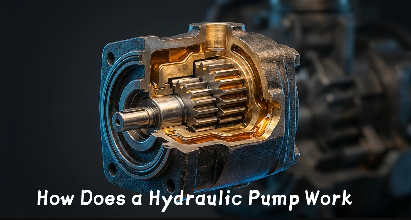
Regardless of type, every hydraulic pump works on the same two-stroke principle. First, an expanding internal volume creates a partial vacuum. Atmospheric pressure then pushes hydraulic fluid from the reservoir into the pump inlet.
Second, that internal volume decreases, forcing the trapped fluid out through the discharge port and into the system. This is the core of how hydraulic fluid flow is generated in any circuit.
One critical concept to internalize: the pump doesn't "make" hydraulic pressure. Pressure only builds when the discharged flow encounters resistance — a load on a cylinder, a restriction in a valve, or a relief valve setting. This principle traces directly back to Pascal's Law, which states that pressure applied to a confined fluid is transmitted equally in all directions.
Types of Hydraulic Pumps and How Each One Works
Gear Pumps — The Workhorse of Hydraulic Systems
The gear pump mechanism is elegantly simple. Two meshing gears rotate inside a tightly-fitted housing. As the gear teeth unmesh on the inlet side, an expanding volume draws fluid in. The fluid gets trapped in the pockets between the gear teeth and the housing wall, then carried around to the outlet side.
When the teeth mesh again at the outlet, the fluid is squeezed out into the discharge line. External gear pumps use two identical gears, while internal gear pumps use a smaller gear inside a larger one, separated by a crescent-shaped seal.
Gear pumps are fixed-displacement devices — they move a set volume of fluid per revolution. They're cost-effective, tolerant of contamination, and well-suited to moderate-pressure applications like log splitters, lubrication systems, and power packs.
Vane Pumps — Balanced Pressure, Smooth Operation
Vane pumps use a slotted rotor spinning inside an eccentric cam ring. Spring-loaded or pressure-loaded vanes slide outward from the rotor slots, maintaining contact with the cam ring's inner surface. As the rotor turns, the eccentricity creates chambers that expand on the inlet side and contract on the outlet side.
Balanced vane pump designs use an elliptical cam ring with two inlet and two outlet ports, which cancels out radial bearing loads and extends service life. Unbalanced designs are simpler but put more stress on shaft bearings.
These pumps run quieter than gear pumps and deliver smoother hydraulic fluid flow. You'll find them in automotive power steering systems, injection molding machines, and machine tools where noise and flow ripple matter.
Piston Pumps — High Pressure, Variable Displacement
When you need high hydraulic pressure and the ability to vary output on the fly, piston pumps are the answer. In an axial piston design, multiple pistons sit in a rotating cylinder block, parallel to the drive shaft. A swashplate (angled plate) causes the pistons to stroke in and out as the block rotates.
The swashplate angle directly controls displacement. Steep angle means long piston stroke and high flow. Zero angle means no stroke and no flow — even at full RPM. This makes axial piston pumps true variable-displacement machines.
Radial piston designs orient the pistons perpendicular to the shaft, with an eccentric cam driving stroke. These handle extremely high pressures but are less common due to size and cost.
You'll see piston pumps on excavators, aircraft flight controls, hydraulic presses, and any system where efficiency and pressure demands justify the higher cost and maintenance complexity.
Comparison Table — Pump Types at a Glance
| Feature | Gear Pump | Vane Pump | Piston Pump |
|---|---|---|---|
| Pressure Range (PSI) | Up to 3,000–4,000 | Up to 3,000 | Up to 6,000–10,000 |
| Displacement Type | Fixed | Fixed or Variable | Fixed or Variable |
| Efficiency (%) | 80–90 | 85–95 | 90–98 |
| Noise Level | Higher | Lower | Moderate |
| Cost | Low | Moderate | High |
| Maintenance Complexity | Simple | Moderate | Complex |
| Common Applications | Log splitters, lubrication systems | Machine tools, plastics injection | Excavators, aircraft, presses |
Step-by-Step — How Hydraulic Fluid Moves Through the System
The Suction Phase (Inlet Stroke)
During the suction phase, the pump's internal element — whether gear teeth unmeshing, vanes passing the inlet, or pistons retracting — expands the available volume inside the pump chamber. This expansion creates a localized low-pressure zone.
Atmospheric pressure (or reservoir pressurization in some systems) pushes fluid from the tank through the inlet line and into the pump. Proper line sizing is critical here. If the inlet is too small, too long, or restricted by a clogged strainer, the pump can't fill completely — and cavitation begins.
Inlet filters and strainers protect the pump but must be maintained. A 75% blocked suction strainer doesn't just reduce flow — it actively damages the pump from the inside out.
The Discharge Phase (Outlet Stroke)
Once the chamber is full, the pump element reduces its volume. Because hydraulic fluid is effectively incompressible, it has nowhere to go but out through the discharge port. This is the positive displacement pump principle in action: every revolution moves a fixed volume, regardless of system pressure.
The discharged fluid travels through directional control valves to actuators — cylinders for linear motion or motors for rotation. Pressure in the system only builds when this flow meets resistance from the load. No load, no pressure. Full load, full pressure (up to the relief valve setting).
System Pressure Regulation and Relief
Every hydraulic system needs overpressure protection. Relief valves act as the safety net, diverting excess flow back to tank when pressure exceeds a set limit. Without them, something in the system will fail catastrophically — usually the weakest hose or fitting.
More sophisticated systems use load-sensing controls that adjust pump output to match actual demand. Variable displacement pumps with pressure compensators automatically de-stroke when system pressure reaches the compensator setting, reducing energy waste and heat generation.
Key Performance Metrics Every Professional Should Monitor
Flow Rate, Displacement, and Volumetric Efficiency
Understanding these numbers lets you diagnose problems before they become failures. Here's your reference:
| Parameter | Formula / Definition | Why It Matters |
|---|---|---|
| Displacement | Volume per revolution (cc/rev or in³/rev) | Determines max flow capacity |
| Theoretical Flow | Displacement × RPM | Baseline output calculation |
| Actual Flow | Theoretical flow minus internal leakage | Real-world system performance |
| Volumetric Efficiency | (Actual flow ÷ Theoretical flow) × 100 | Indicates pump wear and health |
| Overall Efficiency | Volumetric × Mechanical efficiency | Total energy conversion effectiveness |
| Case Drain Flow | Leakage from pump internals to case drain | Early warning of pump degradation |
A new piston pump might run at 95% volumetric efficiency. When that drops to 80%, you're losing real flow — and the pump is telling you it's wearing out. Trending case drain flow over time is one of the most reliable predictive maintenance tools available.
How Fluid Viscosity and Temperature Affect Performance
Every positive displacement pump has an optimal viscosity window. Too thick (cold start conditions) and the pump struggles to fill on the suction side, increasing inlet vacuum and cavitation risk. Too thin (overheated fluid) and internal leakage skyrockets, killing volumetric efficiency.
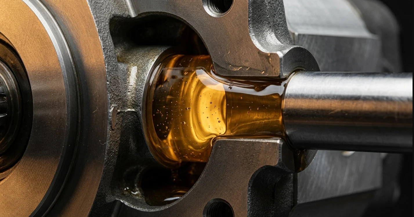
Most hydraulic systems perform best with fluid viscosity between 16 and 36 centistokes at operating temperature. ISO viscosity grade selection (ISO VG 32, 46, or 68) should be based on your expected operating temperature range and the pump manufacturer's recommendations.
Common Failure Modes and What Causes Them
Cavitation — The Silent Pump Killer
Cavitation occurs when the pump's inlet conditions can't keep up with its demand for fluid. Localized low-pressure zones cause dissolved gases or vapor bubbles to form in the fluid. When these bubbles reach the high-pressure discharge side, they implode violently against metal surfaces.
The symptoms are distinctive: a rattling or "marbles in a can" noise, erratic actuator movement, and — if you pull the pump apart — pitting and erosion on gear faces, vane tips, or piston bores. Prevention comes down to proper inlet line sizing, clean suction strainers, correct reservoir fluid levels, and keeping fluid viscosity in range.
Contamination, Aeration, and Wear
Particle contamination remains the leading cause of hydraulic pump failure across all types. Microscopic particles smaller than the human eye can see (under 40 microns) cause the most damage because they're the right size to wedge into clearance gaps in the gear pump mechanism, between vanes and cam rings, or inside piston-bore fits.
Aeration is different from cavitation but equally destructive. Air enters the system through leaky suction fittings, low fluid levels, or turbulent reservoir conditions. Entrained air makes the system spongy and unpredictable, and causes localized overheating when compressed.
Maintaining ISO 4406 cleanliness codes appropriate for your pump type — typically 18/16/13 for gear pumps and 16/14/11 or cleaner for piston pumps — is non-negotiable for long service life.
Selecting the Right Hydraulic Pump for Your Application
Decision Framework — Matching Pump Type to System Demands
Start with your pressure requirement. If you need over 5,000 PSI, you're looking at piston pumps — full stop. For systems running under 3,000 PSI with fixed flow needs, a gear pump delivers reliable performance at the lowest cost.
Next, consider whether you need variable flow. If the system has widely varying demand, a variable displacement piston pump with load-sensing or pressure compensation will save significant energy over a fixed-displacement pump running across a relief valve. The higher purchase price often pays for itself within a year through reduced energy consumption and heat generation.
Don't overlook noise constraints (vane pumps win here), space limitations (gear pumps are compact), duty cycle (piston pumps handle continuous high-pressure duty best), and total cost of ownership over the machine's expected life.
Industry Trends Shaping Pump Technology
Electro-hydraulic integration continues accelerating. Digital displacement pump technology — where individual piston chambers are electronically switched — promises step-change efficiency improvements for off-highway and marine applications.
Smart condition monitoring using IoT-enabled pressure, temperature, and flow sensors is making predictive maintenance accessible even on smaller systems. Real-time efficiency calculations can flag pump degradation months before failure.
Despite growing electrification trends in mobile equipment, hydraulic systems maintain clear advantages in power density for heavy-duty applications. The technology isn't going away — it's getting smarter.
Practical Takeaways for Hydraulic System Professionals
Quick-Reference Maintenance Checklist
- Fluid analysis: Sample every 500–1,000 hours or quarterly — whichever comes first
- Filter changes: Replace based on differential pressure indicators, not just time intervals
- Inlet inspection: Check suction strainers and hose condition monthly
- Case drain trending: Measure and log case drain flow at consistent RPM and pressure — rising trends indicate wear
- Temperature logging: Track operating temperature and investigate any upward drift
- Pressure verification: Confirm relief valve and compensator settings during each major service
Key Principles to Remember
Pumps create flow, not pressure. Pressure is the system's response to load resistance. This single concept prevents countless misdiagnoses.
Every hydraulic pump relies on fluid displacement through expanding and contracting volumes. Whether it's gears, vanes, or pistons doing the work, the physics are the same.
Cleanliness and correct fluid selection prevent the majority of failures. Most pump problems are system problems — contamination, aeration, wrong viscosity, or inadequate inlet conditions.
Match your pump type to application requirements. Over-specifying wastes money upfront. Under-specifying costs far more in downtime and replacements. Get the selection right, maintain the system properly, and a quality hydraulic pump will deliver years of reliable service.



