

Water ranks as the second most destructive contaminant in hydraulic systems, behind only particulate matter. Even small concentrations of moisture accelerate oxidation, strip additive packages, and trigger corrosion cascades that compromise pumps, valves, and actuators. This guide covers professional-grade methods for diagnosing, removing, and preventing hydraulic fluid contamination caused by water ingress.
Whether you manage a fleet of mobile equipment or maintain a centralized hydraulic power unit in a manufacturing plant, the procedures below will help you restore fluid integrity and protect critical assets.
Understanding Water Contamination in Hydraulic Systems
Types of Water Contamination (Dissolved, Emulsified, Free Water)
Water exists in hydraulic oil in three distinct states. Dissolved water is molecularly dispersed within the fluid, invisible to the naked eye, and typically present below the saturation point—often 200–300 ppm depending on base stock and temperature. Emulsified water forms a stable suspension of micro-droplets that gives the fluid a milky or hazy appearance. Free water settles to the lowest points in the reservoir as a separate phase.
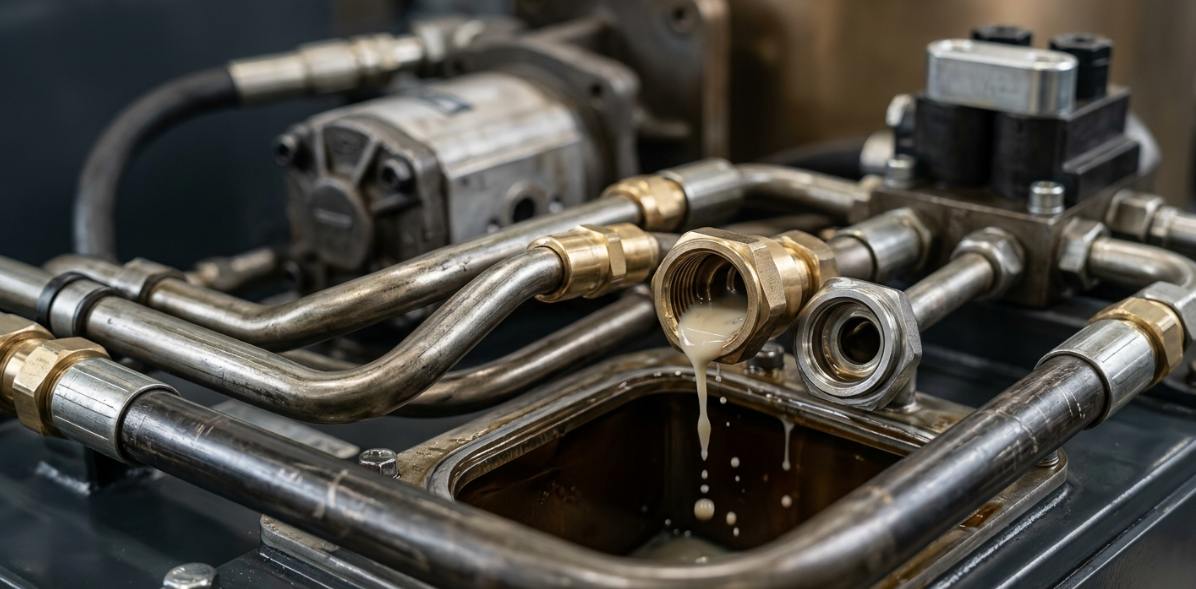
Emulsified water is widely recognized as the most damaging form for component wear. The micro-droplets pass through clearances in pumps and valves, collapsing under pressure and causing micro-pitting and erosion. ISO 4406 cleanliness standards, when paired with moisture specifications, typically call for fewer than 100 ppm in servo-proportional systems and below 200 ppm for general industrial hydraulics.
Common Sources of Water Ingress in Hydraulic Equipment
- Thermal cycling and reservoir breathing: As fluid temperature fluctuates, the reservoir draws ambient air through breathers. Humidity condenses on cooler internal surfaces, introducing moisture with every thermal cycle.
- Failed seals and worn components: Degraded cylinder rod seals, damaged breather caps, and corroded inspection covers create direct pathways for water ingress prevention failures.
- Contaminated replacement fluid: New oil stored in partially filled drums accumulates condensation. Without incoming quality verification, this moisture transfers directly into the system.
- Process water cross-contamination: Heat exchanger tube failures, wash-down spray, and flood events introduce bulk water rapidly.
How Water Damages Hydraulic Components
Water accelerates base oil oxidation by up to ten times at concentrations above 500 ppm. It depletes anti-wear and anti-oxidant additives, cutting effective fluid life by 30–50%. The resulting acid byproducts attack ferrous metals and degrade elastomeric seals.
At the component level, moisture drives cavitation, micro-pitting on bearing surfaces, and hydrogen embrittlement in high-strength steels. Industry data shows that maintaining fluid below target moisture levels can extend component life by two to five times. It also reduces unplanned downtime costs—costs that frequently exceed $10,000 per hour in continuous-process industries.
Diagnosing Water Contamination Levels Before Treatment
Visual and Sensory Indicators of Moisture Presence
A milky or cloudy appearance in hydraulic oil is the classic indicator of emulsified water. Rust-colored deposits on filter elements, reservoir walls, or magnetic plugs point to active corrosion from sustained moisture exposure. Unusual pump whine, erratic actuator movement, or spongy control response may signal moisture-related cavitation or aeration compounded by water.
Laboratory and On-Site Testing Methods
Karl Fischer titration remains the gold standard for precise ppm measurement, offering accuracy within ±5 ppm in accredited labs. For rapid field assessment, the crackle test (heating a drop of oil on a hot plate to observe bubble formation) provides a qualitative pass/fail indication per ASTM D6304 methodology. Calcium hydride test kits deliver portable quantitative readings suitable for maintenance rounds.
For facilities that need continuous monitoring, inline infrared spectroscopy or capacitive moisture sensors provide real-time ppm data with configurable alarm thresholds. This enables predictive responses before contamination reaches critical levels.
Determining the Severity and Appropriate Response
| Contamination Level (ppm) | System Criticality | Recommended Action |
|---|---|---|
| <200 ppm | Standard industrial | Monitor; schedule next sample |
| 200–500 ppm | Any | Treat in-situ (vacuum dehydration or coalescing) |
| >500 ppm | Any | Hydraulic reservoir drainage and full system flush |
| >200 ppm | Servo/proportional | Immediate treatment to <50 ppm target |
When contamination exceeds fluid oxidation or acid number limits—or when dead legs and low points prevent effective in-situ treatment—a complete system flushing procedure becomes the only viable path to restoration.
Method 1 — Vacuum Dehydration (Most Effective for In-Service Systems)
How Vacuum Dehydration Works
Vacuum dehydration works because water's boiling point drops sharply under reduced pressure. At 25 inches of mercury vacuum, water boils at approximately 133°F (56°C)—well below temperatures that would degrade hydraulic oil. The process extracts dissolved, emulsified, and free water simultaneously. It also removes dissolved gases and light volatile contaminants.
Modern vacuum dehydration units routinely reduce moisture content to below 50 ppm in a single pass. This makes it the most effective technology for moisture removal in hydraulic oil applications requiring stringent cleanliness targets.
Step-by-Step Vacuum Dehydration Procedure
- Equipment sizing: Select a unit rated for a minimum flow rate that processes the full system volume every 2–4 hours. For a 200-gallon reservoir, target 50–100 GPH capacity.
- Connection: Configure in a kidney-loop arrangement. Draw from the reservoir's lowest drain point and return fluid to the opposite end above fluid level to maximize exposure.
- Parameter setup: Set inlet temperature to 140–160°F (60–71°C), vacuum level to 25–28 inHg, and flow rate per manufacturer specifications.
- Circulation: Run continuously, sampling at 4-hour intervals. Calculate expected duration based on initial ppm, target ppm, and unit efficiency rating.
- Verification: Confirm final moisture content via Karl Fischer titration before disconnection. Document results for maintenance records.
When to Choose Vacuum Dehydration Over Other Methods
Vacuum dehydration is the preferred choice for large-volume systems, in-service treatment without shutdown, and applications demanding very low ppm targets. Its limitations: higher equipment acquisition cost and the need for trained operators who understand vacuum and temperature relationships.
Method 2 — Coalescing and Absorbent Filtration
Coalescing Separators for Free and Emulsified Water
Coalescing separators use staged hydrophilic and hydrophobic media to merge micro-droplets into larger masses that gravity can separate. These units achieve greater than 95% removal efficiency for free water and handle emulsified contamination well. They have minimal impact on dissolved moisture below saturation levels, though.
Size the coalescer for the system's maximum flow rate with a safety margin. Exceeding rated flow causes bypass—pushing emulsified water past the media bed without adequate residence time for coalescence.
Absorbent Filter Elements for Dissolved Moisture Removal
Super-absorbent polymer (SAP) media elements capture dissolved water through chemical bonding. They work well as a polishing stage after coalescing or as a stand-alone solution for systems slightly above target ppm. Placement options include return-line filter housings, offline filtration carts, and desiccant-style breather filters on reservoirs.
Monitor saturation through visual indicators (color-change elements) or weight gain. Typical SAP elements absorb 30–50 times their weight in water before requiring replacement.
Method 3 — Hydraulic Reservoir Drainage and Complete System Flush
When a Full Drain-and-Flush Is Necessary
Gross contamination events—floods, catastrophic seal failures, coolant breaches—demand complete fluid replacement. The same applies when oil analysis reveals oxidation levels or acid numbers exceeding condemning limits; in-situ treatment cannot restore fluid chemistry. Systems with extensive dead legs, long pipe runs, or inaccessible low points that trap free water also require full evacuation.
System Flushing Procedure — Step by Step
- Safe shutdown: De-energize and depressurize the system. Lock out all energy sources per site-specific LOTO procedures.
- Drain at lowest points: Open all drain valves, remove inspection covers, and tilt or vacuum residual fluid from dead legs and cylinder rod ends.
- Clean reservoir interior: Wipe surfaces with lint-free cloths. Remove sludge, rust, and biofilm. Replace all breather elements and filters.
- Charge with flushing fluid: Use a compatible low-viscosity flush oil. Circulate at turbulent-flow velocity (Reynolds number exceeding 4000) to scour pipe walls and dislodge contaminants.
- Sample and verify: Monitor particle counts and moisture at regular intervals. Continue flushing until fluid meets ISO 4406 and ppm targets for two consecutive samples.
- Final fill: Drain flush oil completely. Charge the system with fresh, pre-filtered hydraulic oil verified for moisture content below 100 ppm at introduction. Bleed air, cycle actuators, and recommission per OEM procedures.
Method 4 — Centrifugal Separation and Headspace Dehumidification
High-Speed Centrifugal Purifiers
Centrifugal separators excel at bulk free-water removal from heavily contaminated fluid. Their throughput makes them suitable for high-volume hydraulic reservoirs where rapid gross decontamination is the priority. Centrifuges struggle with emulsified water, though—stable emulsions resist gravitational separation—and they have no effect on dissolved moisture.
Use centrifugal purification as a first-stage treatment, then follow with vacuum dehydration or absorbent filtration to reach final ppm targets.
Headspace Dehumidifiers and Desiccant Breathers
Preventing re-contamination matters just as much as the initial moisture removal. Headspace dehumidifiers condition the air above the fluid surface, holding relative humidity below 30% to prevent condensation during thermal cycling. Hybrid desiccant breathers combine silica gel or molecular sieve media with particulate filtration, protecting the reservoir from both moisture and airborne particles during every breathing cycle.
Maintain desiccant breathers on a color-change indicator schedule. Regenerable units cut long-term consumable costs for systems with high breathing rates.
Water Ingress Prevention — Long-Term Contamination Control
Sealing and Hardware Upgrades
Upgraded polyurethane rod seals and multi-lip wiper designs significantly reduce water ingress in outdoor, marine, and wash-down environments. Reservoir modifications — sealed expansion bladders or positive-pressure nitrogen blankets — eliminate breathing-related condensation entirely. Regularly inspect shell-and-tube heat exchangers for tube degradation to prevent coolant-to-oil crossover events.
Fluid Monitoring and Predictive Maintenance Programs
Install inline capacitive moisture sensors at the reservoir return line with alarm thresholds set at 50% of condemning limits. This gives early warning before contamination reaches damaging levels. Complement real-time monitoring with scheduled laboratory oil analysis at a quarterly minimum cadence for critical systems.
Trend moisture data alongside particle counts and acid number to build a comprehensive contamination profile. Correlating these parameters reveals developing problems. Rising moisture paired with increasing acid number, for example, indicates accelerated oxidation requiring immediate intervention.
Storage and Handling Best Practices
Store drums sealed and horizontally to prevent water pooling around bungs where condensation collects. Use dedicated transfer carts equipped with desiccant breathers and 3-micron filtration for all top-off operations. Verify incoming fluid quality with a Karl Fischer test before introduction — never assume new oil meets your system's cleanliness specifications.
Frequently Asked Questions (FAQ)
What is the acceptable water content in hydraulic oil?
Most OEMs specify 100–200 ppm as the upper acceptable limit for standard industrial systems. Servo-proportional and high-pressure systems often require below 50 ppm. Always refer to your equipment manufacturer's guidelines and align with ISO 4406 cleanliness codes for your specific application.
Can you just drain and refill to remove water from a hydraulic system?
Draining removes free water pooled at low points. It leaves emulsified and dissolved moisture in residual fluid films coating pipe walls, cylinder bores, and dead legs. A complete system flushing procedure combined with dedicated moisture removal technology — such as vacuum dehydration — is necessary for thorough decontamination. Simple drain-and-refill typically leaves 10–30% of original contamination in place.
How often should hydraulic fluid be tested for moisture?
At minimum, test quarterly for standard industrial systems. Monthly testing suits equipment operating outdoors, in high-humidity environments, or subject to frequent thermal cycling. Critical systems benefit from continuous inline moisture sensors that provide real-time ppm data and automatic alerts when thresholds are approached.
Does water contamination void hydraulic component warranties?
Many manufacturers classify water ingress as a maintenance failure, which can void warranty coverage for pumps, motors, and valves. Maintaining documented oil analysis records that demonstrate consistent moisture control protects warranty claims and supports root-cause investigations when failures occur. Proactive documentation is your strongest defense.
How long does vacuum dehydration take to remove water from hydraulic fluid?
Duration depends on system volume, starting ppm, target ppm, and unit processing capacity. As a practical reference, a typical 200-gallon system starting at 1,000 ppm can reach below 100 ppm within 8–24 hours of continuous kidney-loop circulation. Larger systems or higher initial contamination levels extend the timeline proportionally.
What is the difference between hydraulic fluid contamination from water vs. air?
Water causes corrosion, additive depletion, and lubrication film failure. Entrained air causes cavitation, spongy actuator response, and thermal degradation through adiabatic compression heating. Both require distinct removal methods — dehydration for water, proper system bleeding and anti-foam measures for air — but they share common root causes including poor sealing, thermal cycling, and inadequate reservoir design.



