

If you've ever worked with hydraulic systems, you know that pump displacement is what really drives performance. It doesn't matter if you're dealing with a compact mobile excavator or a high-precision CNC machine — being able to change displacement on the fly makes all the difference in how well your system turns mechanical energy into hydraulic flow. Once you understand how an axial piston pump adjusts its displacement, you gain much better control over flow, pressure, and energy efficiency across both industrial and mobile applications.
In this guide, we'll break down the axial piston pump working principle, explore swashplate angle adjustment mechanics, and examine the control methods that make variable displacement hydraulic pump technology so versatile across industries.
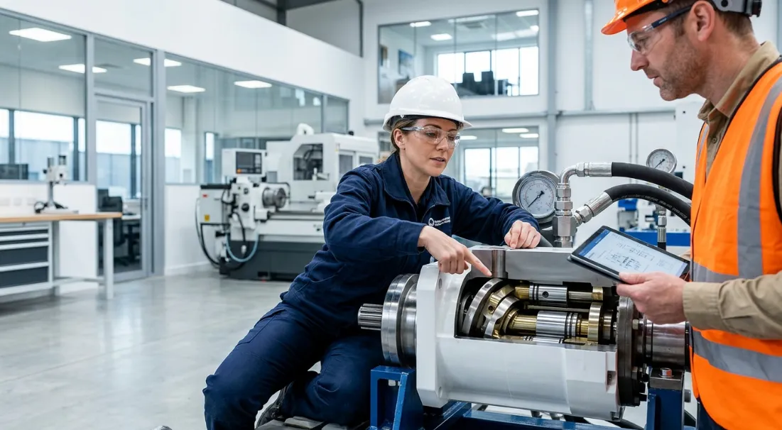
Fundamentals of Axial Piston Pump Working Principle
Core Components and Their Roles
An axial piston pump converts rotational mechanical energy into hydraulic fluid power through a precisely engineered assembly of interdependent components. Each part plays a specific role in enabling the pump's ability to vary its displacement output.
The drive shaft transmits rotational power from the prime mover into the pump housing. It connects directly to the cylinder barrel, which contains multiple cylindrical bores arranged in a circular pattern around the shaft axis.
Inside each bore sits a piston that reciprocates axially as the barrel rotates. The pistons ride against the swashplate (also called a cam plate), an angled surface that converts rotary motion into the linear piston movement responsible for fluid displacement.
The valve plate (or port plate) sits at the opposite end of the cylinder barrel, providing kidney-shaped inlet and outlet ports. As each piston retracts, it draws fluid through the inlet port; as it extends, it pushes fluid out through the outlet port. This component ensures proper timing of suction and discharge cycles.
How Piston Stroke Creates Fluid Displacement
Displacement in an axial piston pump is the total volume of fluid moved per complete revolution of the drive shaft. It's determined by how far each piston travels within its bore during one rotation of the cylinder barrel.
As the barrel rotates, each piston follows the angled surface of the swashplate. During one half of the rotation, the piston retracts (creating suction), and during the other half, it extends (creating discharge). The distance the piston travels from its most retracted to most extended position is the stroke length.
The volumetric output per revolution equals the combined swept volume of all pistons. A pump with nine pistons, each displacing a small volume per stroke, produces a smooth, near-continuous flow. The more pistons and the longer the stroke, the greater the displacement per revolution.
The Role of Swashplate Angle Adjustment in Displacement Change
Swashplate Geometry and Piston Stroke Length
The swashplate angle is the single most influential geometric variable in controlling displacement. When the swashplate sits perpendicular to the drive shaft (zero degrees of tilt), the pistons do not reciprocate at all, and displacement drops to zero.
As the swashplate tilts to a greater angle, the pistons must travel a longer distance during each revolution. This directly increases the stroke length and, consequently, the volume of fluid displaced per rotation. The relationship is essentially linear within the pump's operating range.
Maximum displacement occurs at the pump's maximum designed swashplate angle, typically between 18° and 20° depending on the manufacturer and model. Reducing the angle proportionally reduces displacement, giving operators or control systems the ability to fine-tune output without changing shaft speed.
Variable Displacement Hydraulic Pump Configurations
Two primary architectures achieve variable displacement in axial piston pumps: the swashplate design and the bent-axis design. Both alter piston stroke through geometric changes, but they accomplish this differently.
In a swashplate pump, the cylinder barrel and drive shaft remain coaxial. The swashplate angle changes relative to the barrel, varying piston stroke. This design is compact, allows easy integration of control mechanisms, and supports rapid displacement changes.
In a bent-axis pump, the cylinder barrel itself tilts relative to the drive shaft. The angle between the barrel axis and the shaft axis determines piston stroke. Bent-axis designs typically achieve higher volumetric efficiency and can handle higher pressures, but they are bulkier and slower to adjust displacement.
For most pump flow rate control applications requiring fast, precise adjustment, the swashplate configuration dominates the market due to its responsiveness and compact packaging.
Displacement Control Table
The following table illustrates the direct relationship between swashplate angle and pump displacement output:
| Swashplate Angle (°) | Relative Stroke Length (%) | Displacement (% of Max) | Typical Flow Output |
|---|---|---|---|
| 0 | 0 | 0 | Zero flow |
| 5 | 25 | 25 | Quarter flow |
| 10 | 50 | 50 | Half flow |
| 15 | 75 | 75 | Three-quarter flow |
| 18–20 (max) | 100 | 100 | Full rated flow |
This proportional relationship is what makes the variable displacement hydraulic pump so effective for energy-saving applications. Rather than throttling excess flow, the pump simply produces only what the system demands.
Mechanisms That Control Displacement Change
Mechanical Control (Manual Handwheel/Lever)
The simplest form of displacement control uses a manual handwheel or lever connected directly to the swashplate. The operator physically sets the desired angle, which remains fixed until manually readjusted.
This approach suits applications where flow demand is constant or changes infrequently. Examples include fixed-speed industrial presses or conveyor drives where the pump runs at a single displacement setting during operation. The advantages are simplicity, low cost, and reliability, but the lack of automatic adjustment limits energy efficiency in variable-demand systems.
Hydraulic Servo Control (Pressure-Compensated)
Pressure-compensated control is the most common automatic displacement adjustment method in industrial hydraulics. It uses a servo piston acting on the swashplate, balanced against a bias spring that holds the pump at maximum displacement by default.
When system pressure reaches the compensator setting, pilot pressure acts on the servo piston to reduce the swashplate angle. This decreases displacement and flow output until only enough flow is produced to maintain the set pressure. The pump effectively becomes a constant-pressure, variable-flow source.
This mechanism responds within 50–200 milliseconds, making it suitable for general industrial circuits. It dramatically reduces energy waste compared to fixed-displacement pumps paired with relief valves, since the pump only produces the flow the system actually consumes.
Electronic Displacement Control (EDC)
Electronic displacement control represents the highest level of pump flow rate control precision. A proportional solenoid or servo valve positions the swashplate based on an electrical command signal, typically 4–20 mA or ±10 V.
A closed-loop controller continuously compares the commanded displacement with actual swashplate position (measured by an LVDT or similar sensor) and corrects any deviation in real time. Response times drop below 30 milliseconds, enabling precise synchronization with machine cycles.
EDC systems excel in applications demanding rapid, repeatable displacement changes: CNC machining centers, plastic injection molding machines, and mobile equipment requiring load-sensing or power-limiting control. They integrate seamlessly with PLCs and machine controllers for fully automated hydraulic management.
Control Methods Comparison Table
| Control Method | Response Time | Precision | Best Application |
|---|---|---|---|
| Mechanical | Slow | Low | Fixed-speed industrial |
| Hydraulic servo | Medium (50–200 ms) | Medium | Pressure-compensated circuits |
| Electro-hydraulic | Fast (30–80 ms) | High | CNC, injection molding |
| Full electronic (EDC) | Very fast (<30 ms) | Very high | Mobile machinery, robotics |
Factors Affecting Displacement and Hydraulic Pump Volumetric Efficiency
Internal Leakage and Clearance Losses
No hydraulic pump delivers 100% of its theoretical displacement as useful output flow. Internal leakage paths exist between the pistons and cylinder bores, across the valve plate face, and through the swashplate slipper pads.
As operating pressure increases, the pressure differential driving leakage flow also increases. This means a pump operating at 350 bar loses a greater percentage of its theoretical displacement to internal leakage than the same pump at 100 bar. Hydraulic pump volumetric efficiency typically ranges from 92% to 98% depending on pressure, speed, and pump condition.
Tighter manufacturing tolerances reduce leakage but increase cost and sensitivity to contamination. Engineers must balance efficiency against durability and cost for each application.
Fluid Viscosity and Temperature Effects
Hydraulic fluid viscosity directly impacts internal leakage rates and, therefore, effective displacement delivery. As oil temperature rises, viscosity drops, and fluid passes more easily through internal clearances.
A pump that delivers 95% volumetric efficiency at 40°C oil temperature might drop to 90% or lower at 80°C with the same fluid. This represents a real reduction in the system's effective displacement, even though the geometric displacement (swashplate angle) hasn't changed.
Proper fluid selection, adequate cooling systems, and temperature monitoring are essential for maintaining consistent displacement delivery across operating conditions.
Wear, Contamination, and Maintenance Impact
Over thousands of operating hours, internal components wear. Piston-to-bore clearances increase, valve plate surfaces develop micro-scoring, and slipper pads lose their hydrostatic bearing effectiveness. Each of these degradation modes permanently increases internal leakage.
Contamination accelerates this process dramatically. Particles as small as 5 microns can damage the precision-lapped surfaces inside an axial piston pump. Once clearances open beyond design limits, no amount of swashplate angle adjustment can recover the lost displacement capacity.
Regular fluid analysis, proper filtration (typically 3–10 micron absolute), and scheduled maintenance intervals are the primary defenses against displacement loss over the pump's service life.
Efficiency Factors Table
| Factor | Effect on Displacement | Mitigation Strategy |
|---|---|---|
| High operating pressure | Increases internal leakage | Tighter tolerances, case drain monitoring |
| Elevated temperature | Reduces volumetric efficiency | Cooling systems, proper fluid selection |
| Contamination | Accelerates wear, increases clearance | Filtration, regular fluid analysis |
| Component wear | Permanent displacement loss | Scheduled maintenance, replacement |
Calculating Displacement Change
Displacement Formula
The theoretical displacement of an axial piston pump can be calculated using the following formula:
D = A × d × n × tan(α)
- D = displacement per revolution (cm³/rev or cc/rev)
- A = piston area (cm²)
- d = pitch circle diameter (cm) — the diameter of the circle on which piston centers are arranged
- n = number of pistons
- α = swashplate angle (degrees)
This formula clearly shows that displacement is directly proportional to the tangent of the swashplate angle. Since tan(α) increases as the angle increases, tilting the swashplate further produces a proportionally larger displacement.
Practical Calculation Example
Consider an axial piston pump with the following specifications:
- Piston diameter: 20 mm (area = 3.14 cm²)
- Pitch circle diameter: 76 mm (7.6 cm)
- Number of pistons: 9
- Shaft speed: 1500 rpm
At a swashplate angle of 10°:
D = 3.14 × 7.6 × 9 × tan(10°) = 3.14 × 7.6 × 9 × 0.176 = 37.8 cm³/rev
Flow rate (Q) = D × speed = 37.8 cm³/rev × 1500 rev/min = 56,700 cm³/min = 56.7 L/min
At a swashplate angle of 18°:
D = 3.14 × 7.6 × 9 × tan(18°) = 3.14 × 7.6 × 9 × 0.325 = 69.8 cm³/rev
Flow rate (Q) = 69.8 × 1500 = 104,700 cm³/min = 104.7 L/min
By increasing the swashplate angle from 10° to 18°, displacement nearly doubles from 37.8 to 69.8 cm³/rev, and flow output increases from 56.7 to 104.7 L/min — all without changing shaft speed. This demonstrates the power of swashplate angle adjustment for on-demand pump flow rate control.
Note: Actual delivered flow will be slightly lower than these theoretical values due to hydraulic pump volumetric efficiency losses, typically 3–8% depending on operating pressure and pump condition.
Frequently Asked Questions
What determines the maximum displacement of an axial piston pump?
The maximum displacement is set by four geometric factors: the maximum swashplate angle (limited by mechanical design), the number of pistons in the cylinder barrel, the piston diameter (which determines swept area), and the pitch circle diameter. Manufacturers design these parameters to achieve a specific rated displacement, and the maximum swashplate angle represents the physical upper limit of the pump's output capacity.
Can an axial piston pump achieve zero displacement?
Yes. When the swashplate angle is set to zero degrees (perpendicular to the shaft axis), the pistons no longer reciprocate within their bores. With zero stroke length, no fluid is displaced regardless of shaft speed. This capability allows variable displacement pumps to remain running at full speed while producing no flow, which is useful for standby conditions and reduces energy consumption compared to unloading through a relief valve.
How does displacement change affect system pressure?
Displacement itself does not create pressure — pressure results from resistance to flow. However, reducing displacement while the system still demands flow (due to actuator loads) causes system pressure to rise until a relief valve or pressure compensator intervenes. Conversely, increasing displacement beyond what the system can accept also drives pressure up. Proper control strategies match displacement to actual flow demand to maintain stable, efficient operation.
What is the difference between fixed and variable displacement axial piston pumps?
Fixed displacement axial piston pumps have a swashplate locked at a single angle, producing constant output flow at any given speed. Variable displacement pumps incorporate a movable swashplate with a control mechanism that allows real-time angle adjustment. This enables on-demand pump flow rate control, where the pump produces only the flow the system requires, significantly improving energy efficiency in applications with varying demand cycles.
How does volumetric efficiency relate to actual displacement?
Actual delivered flow equals the theoretical displacement multiplied by volumetric efficiency. For example, a pump with 100 cm³/rev geometric displacement and 95% volumetric efficiency delivers only 95 cm³/rev of useful flow. The remaining 5% is lost to internal leakage. Volumetric efficiency decreases with higher pressure, higher temperature, and component wear, meaning the effective displacement a system receives is always somewhat less than the geometric maximum set by the swashplate angle.



