

If you've ever watched a hydraulic excavator hoist a 20-ton slab off the ground, or wondered how an aircraft's flight controls move with split-second precision, the answer traces back to one component: the variable displacement piston pump. It takes mechanical rotation and turns it into hydraulic flow you can dial in with real accuracy. Get a handle on how it works, and you start to see the levers behind efficiency, performance, and smarter system design.
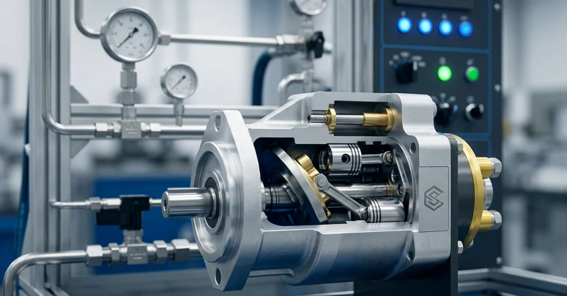
This technical treatise presents a rigorous analysis of variable displacement hydraulic pump operation, systematically examining fundamental component architecture, governing principles, and empirical performance characteristics to furnish engineers and practitioners with the authoritative knowledge requisite for precise specification, optimal operation, and effective maintenance of these indispensable fluid power systems.
What Is a Variable Displacement Piston Pump?
A variable displacement piston pump is a positive-displacement hydraulic pump whose output flow can be adjusted continuously — from zero to maximum — without changing the input shaft speed. This is the fundamental distinction from a fixed displacement pump, which delivers a constant volume per revolution regardless of system demand.
The core concept is elegantly simple: by changing the stroke length of reciprocating pistons inside a rotating cylinder block, the piston pump flow rate adjustment happens mechanically in real time. This allows the hydraulic system to deliver only the energy actually needed, dramatically reducing waste.
Fixed vs. Variable Displacement — Key Differences
Before diving into the working principle, it helps to understand why variable displacement pumps exist alongside their simpler fixed-displacement counterparts.
| Parameter | Fixed Displacement Pump | Variable Displacement Pump |
|---|---|---|
| Flow Control Method | Throttling or bypass valve | Internal displacement adjustment |
| Energy Efficiency | 50–70% (system level) | 80–94% (system level) |
| Heat Generation | High (excess flow over relief) | Low (only pumps what is needed) |
| Initial Cost | Lower (1× baseline) | Higher (2–3× baseline) |
| Complexity | Simple, fewer moving parts | Complex control mechanisms |
| Typical Applications | Constant-demand systems, power packs | Mobile equipment, industrial presses, aerospace |
Types of Variable Displacement Piston Pumps
Variable displacement piston pumps come in several configurations, each suited to specific operating conditions:
- Axial piston — swashplate design: The most common type. Pistons are parallel to the drive shaft, and a tilting swashplate controls stroke length. Dominates mobile hydraulics and industrial applications due to compact size and fast response.
- Axial piston — bent-axis design: The cylinder block is angled relative to the drive shaft. Offers higher efficiency (up to 95%) and better high-pressure performance. Common in heavy-duty industrial and transmission applications.
- Radial piston: Pistons arranged radially around an eccentric cam. Excels at very high pressures (up to 700 bar) and low speeds. Found in presses, machine tools, and wind turbine pitch systems.
For the remainder of this article, we focus primarily on the axial piston swashplate design, as it represents over 70% of variable displacement piston pumps in service worldwide.
Core Components and Their Functions
Understanding the working principle requires familiarity with each internal component. The swashplate angle control mechanism and cylinder block assembly work together as a precision fluid-displacement system.
Component Breakdown Table
| Component | Function | Material (Typical) |
|---|---|---|
| Cylinder block (barrel) | Houses pistons in precision bores; rotates with drive shaft | Case-hardened steel |
| Pistons | Reciprocate within bores to draw in and expel fluid | Tool steel / ceramic-coated |
| Swashplate / yoke | Controls piston stroke length by tilting angle | Hardened alloy steel |
| Valve plate (port plate) | Directs flow between suction and discharge ports | Bronze / bimetallic |
| Drive shaft | Transmits mechanical input from prime mover | Alloy steel |
| Bias spring / servo piston | Adjusts and holds swashplate angle per control signal | Spring steel / aluminum |
| Slipper pads | Maintain contact between pistons and swashplate face | Bronze on steel backing |
| Housing | Contains and supports all internals; provides mounting | Cast iron / aluminum |
Each component must maintain extremely tight tolerances — piston-to-bore clearances are typically 5–10 micrometers. This precision is what enables volumetric efficiencies above 95% in new pumps.
Step-by-Step Working Principle
The variable displacement hydraulic pump operation follows a continuous rotary cycle with three overlapping phases. As the cylinder block rotates, each piston sequentially passes through suction, transition, and discharge zones defined by the valve plate geometry.
Phase 1 — Suction (Intake) Stroke
As the cylinder block rotates, each piston passes over the low-pressure kidney-shaped port in the valve plate. The swashplate geometry forces the piston to retract within its bore, increasing the chamber volume.
This volume increase creates a localized pressure drop below the reservoir pressure, drawing hydraulic fluid into the expanding bore through the suction port. The intake continues for approximately 180° of shaft rotation.
Key point: no mechanical valves open or close during this process. The valve plate's fixed geometry and the cylinder block's rotation handle all flow timing passively — a major reliability advantage.
Phase 2 — Discharge (Pressure) Stroke
As the piston crosses the transition zone (a narrow land between the two kidney ports), it begins traveling toward the valve plate face. The swashplate's angled surface pushes the piston inward, compressing the trapped fluid.
Once the bore aligns with the high-pressure kidney port, the pressurized fluid is expelled into the system discharge line. The piston continues its inward stroke for approximately 180° of rotation, delivering flow at system pressure.
The axial piston pump displacement volume per revolution equals the total swept volume of all pistons combined. In a typical 9-piston pump with 63 cc/rev maximum displacement, each piston displaces approximately 7 cc per stroke at full angle.
Phase 3 — Displacement Control (Swashplate Angle Adjustment)
This is where the "variable" in variable displacement becomes operational. A servo mechanism — typically a hydraulic actuator opposed by a bias spring — tilts the swashplate to change the piston stroke length.
At maximum swashplate angle (typically 15–18°), pistons travel their full stroke, delivering maximum displacement. At zero angle, the swashplate is perpendicular to the shaft, pistons do not reciprocate, and output flow drops to zero — the pump is fully de-stroked.
The swashplate angle control mechanism responds in 30–80 milliseconds in modern pumps, enabling rapid adaptation to changing system demands. This response time is critical in applications like excavator boom control where operator feel depends on immediate flow response.
Flow Rate Relationship
The relationship between swashplate angle and output flow is essentially linear. The following table demonstrates this for a typical 63 cc/rev axial piston pump:
| Swashplate Angle (°) | Displacement (cc/rev) | Flow at 1800 RPM (L/min) | Approx. Overall Efficiency (%) |
|---|---|---|---|
| 0 | 0 | 0 | — |
| 5 | 18 | 32 | 88 |
| 10 | 36 | 65 | 91 |
| 15 | 54 | 97 | 93 |
| 18 (max) | 63 | 113 | 92 |
Note: Efficiency peaks at approximately 75% of maximum displacement due to optimized bearing loads and leakage ratios. At very low displacements, volumetric efficiency drops because internal leakage becomes a larger percentage of total flow.
The governing equation is: Q = D × n × ηv, where Q is flow rate (L/min), D is displacement (cc/rev), n is speed (RPM), and ηv is volumetric efficiency.
Control Mechanisms for Displacement Variation
The intelligence of a variable displacement piston pump lies in its control system. Multiple control strategies exist, each optimized for different operating scenarios. The hydraulic pump pressure compensation approach is the most widely used, but modern systems often combine multiple control modes.
Pressure Compensator Control
A pressure compensator maintains a preset maximum system pressure by automatically de-stroking the pump when downstream demand drops. When system pressure reaches the compensator setting (e.g., 250 bar), a pilot signal overcomes the bias spring and tilts the swashplate toward zero displacement.
This eliminates the massive energy waste of a fixed-displacement pump dumping excess flow over a relief valve. Real-world measurements show energy savings of 30–50% in cyclic-duty applications like injection molding machines, where hold phases require pressure but minimal flow.
The compensator acts as a proportional controller — it does not simply switch between full flow and zero flow. Instead, it modulates displacement to maintain the set pressure within a narrow deadband (typically ±5 bar).
Load-Sensing Control
Load-sensing (LS) control takes efficiency a step further by matching pump output to the actual load pressure plus a fixed pressure margin — typically 14–21 bar (200–300 psi) above the highest load signal in the system.
A shuttle valve network reports the highest actuator load pressure back to the pump's LS port. The pump then adjusts displacement to maintain only enough pressure to move that load plus overcome valve and line losses. When no actuator is commanded, the pump de-strokes to standby flow (typically 2–4 L/min).
Load-sensing systems are the standard in modern mobile hydraulics. A typical 20-ton excavator with load-sensing pumps consumes 15–25% less fuel than an equivalent machine with open-center fixed-displacement hydraulics.
Electronic Displacement Control (EDC)
Electronic displacement control replaces hydro-mechanical feedback with a proportional solenoid and electronic controller. A position sensor on the swashplate provides closed-loop feedback, enabling precise displacement commands via CAN-bus or analog signals.
EDC enables programmable flow profiles, remote diagnostics, and integration with machine management systems. Response times improve to 20–40 milliseconds, and displacement accuracy reaches ±1% of commanded value.
Modern Tier 4 and Stage V construction equipment relies heavily on EDC to coordinate pump displacement with engine speed maps, optimizing fuel efficiency across the entire operating envelope.
Horsepower (Torque) Limiting
Horsepower limiting prevents the prime mover from stalling under high-load conditions. As system pressure rises, the control automatically reduces displacement to keep the product of pressure × displacement (which is proportional to torque) below the engine's available power.
This follows a constant-power hyperbola: at 350 bar, the pump might deliver 40 L/min, while at 175 bar it delivers 80 L/min — same power consumption in both cases. This allows full utilization of the prime mover across all operating conditions without oversizing the engine.
Performance Data and Real-World Specifications
Selecting the right pump requires comparing specifications across manufacturers. The following data represents current-production models widely used in industrial and mobile applications.
Industry Benchmark Comparison Table
| Parameter | Bosch Rexroth A10VO | Parker PV Series | Eaton 420 Series |
|---|---|---|---|
| Displacement range (cc/rev) | 18–140 | 16–140 | 23–130 |
| Max continuous pressure (bar) | 350 | 350 | 350 |
| Max speed (RPM) | 3,000 | 3,000 | 3,100 |
| Overall efficiency (%) | 91–94 | 90–93 | 89–92 |
| Noise level dB(A) | 72–78 | 74–80 | 75–81 |
| Control options | PC, LS, EDC, HP limit | PC, LS, EDC, HP limit | PC, LS, HP limit |
| Weight range (kg) | 12–65 | 11–60 | 14–58 |
Data sourced from manufacturer catalogs (2023–2024 editions). Actual performance varies with operating conditions, fluid viscosity, and system configuration.
All three manufacturers achieve remarkably similar peak performance, reflecting decades of refinement in axial piston technology. Differentiators tend to be control flexibility, service network availability, and integration with specific machine platforms.
Advantages and Limitations
Advantages
- Energy savings of 30–50% over fixed displacement pumps in cyclic-duty applications, directly reducing fuel consumption and operating costs.
- Reduced heat generation — less wasted energy means smaller oil coolers, smaller reservoirs, and longer fluid life.
- Precise flow and pressure control — enables smooth actuator motion, accurate positioning, and multi-function coordination.
- Extended component life — lower average operating pressures reduce stress on hoses, fittings, cylinders, and motors throughout the system.
- Smaller system footprint — one variable pump can replace multiple fixed pumps and their associated valving.
Limitations
- Higher initial cost: 2–3× the price of an equivalent fixed displacement pump, though lifecycle cost is typically lower.
- Greater maintenance complexity: More internal components, tighter tolerances, and sophisticated controls require skilled technicians.
- Sensitivity to fluid contamination: ISO 18/16/13 cleanliness or better is recommended. Contamination accelerates wear on slipper pads, valve plates, and servo components.
- Minimum speed limitations: Most swashplate pumps require at least 500–800 RPM for adequate hydrodynamic lubrication of the slipper/swashplate interface.
Common Applications
The versatility of variable displacement piston pumps makes them the preferred choice wherever hydraulic systems face varying load and flow demands.
Application Matrix
| Industry | Application | Why Variable Displacement? |
|---|---|---|
| Construction | Excavators, wheel loaders, cranes | Multi-actuator load-sensing efficiency; fuel savings |
| Aerospace | Flight control hydraulics, landing gear | Precise, weight-critical flow control; redundancy |
| Manufacturing | Injection molding, metal forming presses | Energy savings during hold/dwell phases (up to 50%) |
| Marine | Deck cranes, steering gear, winches | Variable speed demand; space and weight constraints |
| Agriculture | Tractors, combine harvesters | Power management across multiple implements |
| Mining | Haul trucks, drill rigs | High-pressure capability; torque limiting for engine protection |
In construction alone, the global market for variable displacement piston pumps exceeds $3 billion annually, driven by emissions regulations that demand higher hydraulic efficiency to meet engine downsizing targets.
Maintenance Best Practices
Maximizing the lifespan of a variable displacement piston pump requires disciplined maintenance focused on three critical areas:
Fluid Cleanliness: Target ISO 18/16/13 or better. Install 10-micron absolute return-line filters and 3-micron kidney-loop filtration. Contamination is responsible for over 70% of premature pump failures. Sample fluid every 500 hours and trend particle counts.
Swashplate Bearing Inspection: Check servo response time and swashplate bearing play at 5,000-hour intervals. Increased control hysteresis or sluggish response indicates bearing wear or servo seal degradation. Replace bearings proactively rather than waiting for catastrophic failure.
Case Drain Flow Monitoring: Case drain flow is the single best health indicator for a piston pump. Establish a baseline at commissioning and monitor quarterly. An increase of more than 1 L/min above baseline signals significant internal leakage from worn pistons, bores, or valve plate surfaces. At 2× baseline, schedule a rebuild.
Pro tip: Install a case drain flow meter permanently on critical pumps. The $200 investment in a flow meter can prevent $15,000+ in unplanned downtime and secondary damage from a catastrophic pump failure.
Frequently Asked Questions
How does a variable displacement piston pump save energy?
It reduces output flow when full flow is not needed, so the prime mover does less work and generates less waste heat. Unlike a fixed displacement pump that continuously dumps excess flow over a relief valve (converting hydraulic energy directly into heat), a variable pump simply produces less flow. In cyclic applications like injection molding, measured energy savings range from 30–50% compared to fixed displacement systems.
What causes a variable displacement pump to lose efficiency?
The primary causes are internal leakage from worn piston-to-bore clearances, degraded valve plate sealing surfaces, worn slipper pads, and contaminated hydraulic fluid accelerating abrasive wear. Elevated case drain flow is the earliest measurable symptom. Operating with fluid above 80°C or below recommended viscosity ranges (13–36 cSt at operating temperature) also degrades volumetric efficiency significantly.
Can you convert a fixed displacement pump to variable displacement?
No — the internal architecture is fundamentally different. A variable displacement pump requires a tilting swashplate, servo actuator, control valves, feedback mechanisms, and a housing designed to accommodate swashplate movement. These cannot be retrofitted into a fixed-displacement housing. The correct approach is to replace the entire pump unit.
What is the typical lifespan of a variable displacement piston pump?
With proper maintenance and clean fluid (ISO 18/16/13 or better), 10,000–20,000 operating hours is common in industrial applications running at moderate pressures. Mobile equipment typically sees 6,000–12,000 hours due to harsher conditions, higher contamination exposure, and more frequent pressure spikes. Premium pumps in well-maintained industrial systems have documented service lives exceeding 30,000 hours.
What hydraulic fluid is recommended?
ISO VG 32–68 mineral-based hydraulic fluid with anti-wear additives (HLP or HM classification per DIN 51524) is the standard recommendation. Fluid viscosity at operating temperature should remain between 13–36 cSt for optimal efficiency and film strength. Synthetic fluids (PAO or ester-based) extend the operating temperature range and service intervals but cost 3–5× more than mineral oils.
How do I size a variable displacement piston pump for my system?
Calculate your maximum required flow rate (L/min) at the actuator, accounting for valve and line losses. Determine maximum system pressure (bar) including pressure drops across filters and valves. Select a pump whose maximum displacement at your operating speed meets or exceeds the flow demand with a 10–15% margin. Verify that the required power (P = Q × p ÷ 600) does not exceed your prime mover's available output, and apply horsepower limiting if needed.
Take the Next Step in Hydraulic System Design
Understanding the working principle of variable displacement piston pumps is the foundation for designing efficient, responsive, and reliable hydraulic systems. Whether you are specifying a pump for a new machine or optimizing an existing system, the right pump selection directly impacts energy consumption, productivity, and total cost of ownership.
Ready to specify the right variable displacement piston pump for your system? Download our free hydraulic pump sizing worksheet to calculate your exact displacement, pressure, and flow requirements. Or contact our engineering team directly for a personalized recommendation tailored to your duty cycle, environmental conditions, and performance targets.
Every percentage point of efficiency gained at the pump translates to measurable fuel savings, reduced emissions, and longer component life across your entire hydraulic circuit. Start optimizing today.



