A technical deep-dive for plant managers, procurement engineers, and maintenance specialists evaluating progressive cavity technology for viscous, abrasive, or shear-sensitive fluid handling.
Why Eccentric Screw Pumps Still Dominate Difficult Fluid Applications
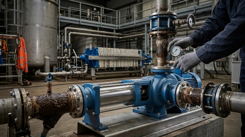
A municipal digester operator swaps a centrifugal pump for the third time in eighteen months because 50,000 cP dewatered sludge keeps shearing the impeller and blocking the suction eye. Two weeks after installing an eccentric screw pump with a 17-4 PH rotor and NBR stator, the same line is running at steady 12 m³/h with no cavitation, no pulsation, and no operator intervention. That is the reason plants keep converting — not fashion, but the physics of positive displacement.
After reading this guide, you should be able to specify a progressive cavity pump for a given fluid, interpret manufacturer curves against your process conditions, identify why an installed unit is underperforming, and build a defensible total cost of ownership case against gear, lobe, and centrifugal alternatives.
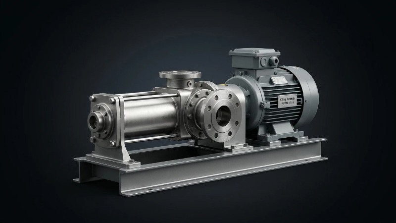
Terminology note: "eccentric screw pump", "progressive cavity pump", "PC pump", and "single-rotor helical pump" all describe the same machine. This article uses the terms interchangeably to reflect how they appear in tenders across European, Middle Eastern, and Southeast Asian markets.
Key Takeaways
- Principle in one sentence: a metal single-helix rotor turns eccentrically inside a double-helix elastomer stator, creating sealed cavities that progress axially from suction to discharge.
- Flow and pressure envelope: 0.1–500 m³/h standard, up to 800 m³/h in large frames; 6 bar per stator stage, stacked up to 48 bar in four-stage builds.
- Ideal fluids: viscous (up to 1,000,000 cP), abrasive (up to 60% solids), or shear-sensitive — sludge, slurry, adhesives, cosmetics, food pastes.
- Dominant wear items: the stator elastomer (8,000–20,000 hours) and rotor coating; joints and seals inspected every ~4,000 hours.
- MTBF drivers: correct elastomer selection, rotor tip speed under 1.5 m/s for abrasives, dry-run protection, and NPSH margin.
- Where PC pumps win: anywhere a centrifugal cavitates, a gear pump wears out on solids, or a lobe pump shears the product.
What Is an Eccentric Screw Pump? A Working Definition
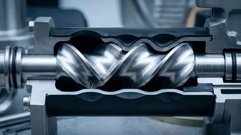
An eccentric screw pump is a rotary positive displacement pump in which a single-helix metal rotor turns eccentrically inside a double-helix elastomer stator. The mismatched helices form a chain of sealed cavities that move axially from suction to discharge with each rotation, delivering a near-constant flow proportional to shaft speed.
How It Differs from Twin-Screw and Gear Pumps
Twin-screw pumps use two intermeshing metal screws with no elastomer, giving them higher speeds and cleaner geometry but poorer solids tolerance. Gear pumps rely on tight metal-to-metal clearances that abrasive particles erode within hours. A PC pump seals through elastomer interference fit, which is why it tolerates 30% solids and shears the fluid an order of magnitude less than either alternative.
Standards and Compliance Context
Serious procurement specifications reference ISO 9001 for manufacturing quality, API 676 for positive displacement rotary pumps, ATEX and CE marking for European hazardous-area service, and EHEDG or 3-A for hygienic duties. Middle Eastern oil and gas buyers typically add NACE MR0175 for sour service wetted components, while Southeast Asian palm oil and mining tenders emphasize CE plus in-house hydrostatic and performance test certificates.
The Working Principle Explained Step by Step
Rotor and Stator Geometry: The Core of Progressive Cavity Action
The rotor is a single-start helix (n lobes = 1); the stator bore is a double-start helix (n+1 = 2). This 1:2 lobe ratio is the geometric requirement for continuous sealed cavities. Because the rotor centerline is offset from the stator centerline by an eccentricity e, the rotor axis traces a small circle as the shaft turns.
Two parameters govern displacement: the eccentricity e and the stator pitch length Ps (twice the rotor pitch). Displacement per revolution is approximately 4 · e · D · Ps, where D is the rotor cross-section diameter. Doubling eccentricity roughly doubles flow at the same speed but also doubles the bending load on the rotor.
Cavity Formation and Fluid Transport Sequence
- At the suction end, a cavity opens between rotor and stator as the rotor rotates into its eccentric position.
- Atmospheric or feed pressure pushes fluid into the opening cavity — self-priming action develops here, up to about 8.5 m of vertical lift on cold water equivalent.
- Once sealed by the interference contact line, the cavity moves axially toward the discharge; volume stays constant, so no compression, no shear spike.
- A mirror cavity on the opposite side of the rotor performs the same transport, phase-shifted by half a pitch.
- At the discharge, the cavity opens against system pressure and the fluid is expelled.
Because two cavities are always in transit, flow pulsation typically stays below 5% — an order of magnitude smoother than a triplex piston pump and clean enough for coating, dosing, and metering duties.
Volumetric Displacement and Sample Flow Table
| Rotor Nominal Size | Eccentricity (mm) | Pitch Ps (mm) | Displacement per Rev (L) | Typical Flow @ 400 rpm (m³/h) |
|---|---|---|---|---|
| L1 | 4 | 40 | 0.05 | 1.2 |
| L2 | 6 | 60 | 0.18 | 4.3 |
| L4 | 10 | 100 | 0.85 | 20.4 |
Values are illustrative — always verify against the manufacturer's slip-corrected curve for your specific viscosity and discharge pressure.
Pressure Build-Up Across Stages
Each stator stage — one full pitch of interference sealing — supports roughly 6 bar of differential pressure before slip becomes uneconomic. Higher discharge pressures come from stacking stages: a two-stage machine handles ~12 bar, a four-stage ~24 bar, and specialized eight-stage builds reach 48 bar for filter-press feed, boiler injection, or long-distance sludge transfer.
Design Features That Define Performance
Rotor Materials and Surface Treatments
Base metals typically include tool steel 1.7225, 17-4 PH stainless, and duplex 1.4462 for chloride-rich service. Wear resistance comes from the surface: hard chrome plating (HV 900–1100) is the workhorse; tungsten carbide HVOF coatings (HV 1200+) are specified for silica sand slurries and drilling mud where chrome would strip within a year.
Stator Elastomers: The Most Underestimated Spec
Field failures blamed on "the pump" are, more often than not, failures of elastomer selection. The stator must resist chemical attack, temperature swings, and swell — because a stator that swells 5% loses its interference fit and the pump slips, or worse, seizes.
| Elastomer | Temp Range (°C) | Best For | Avoid With |
|---|---|---|---|
| NBR | -20 to 90 | Mineral oils, wastewater, general industrial | Aromatics, ozone, ketones |
| HNBR | -30 to 130 | Sour crude, elevated temperature oils | Ketones, strong acids |
| EPDM | -40 to 120 | Hot water, acids, caustics, hygienic | Mineral oils, fuels |
| FKM (Viton) | -20 to 180 | Aggressive chemicals, aromatics, solvents | Amines, hot water >100 °C |
| Natural Rubber | -30 to 70 | Highly abrasive slurries, tailings | Oils, high temperature |
Joint Design: Pin Joint vs. Gear Joint vs. Flex Shaft
The rotor's eccentric motion must be transferred from a concentric drive shaft — that is the joint's job. Pin joints (bushing plus cross-pin) are simple, low-cost, and rebuildable, rated for moderate torque. Gear joints (crowned gear couplings in an oil-filled boot) carry roughly 2× the torque and survive high-pressure duties, at higher cost and stricter sealing demand. Flex-shaft designs eliminate joints entirely by using a slender spring-steel rod to absorb eccentricity — ideal for hygienic and low-torque applications where cleanability trumps torque capacity.
Sealing Options at the Drive End
Gland packing is inexpensive and drips by design (~10–30 drops/min) — acceptable for water and neutral fluids. Single mechanical seals are the mainstream choice for chemicals and light hydrocarbons. Double mechanical seals with an API Plan 53 barrier fluid loop are mandatory for toxic, flammable, or ATEX Zone 1 duties. Lip seals appear only on the lightest utility duties.
Drive Train and Bearing Housing
The bearing housing carries axial thrust generated by discharge pressure acting on the rotor projected area — often overlooked in sizing. Oil-bath lubrication with a sight glass supports higher speeds and longer L10 bearing life than grease packing, and a properly sized housing should push bearing L10 well beyond the stator service interval, so bearings are never the bottleneck.
Port Configuration and Hopper Variants
Standard suction and discharge flanges follow DIN, ANSI, or SAE patterns per market. For pastes above 100,000 cP — filter cake, thickened sludge, cosmetic creams — an open-hopper design with a horizontal auger feed screw force-feeds product into the pumping element, eliminating the bridging that would otherwise starve the suction cavity.
Performance Envelope and Application Fit
Typical Operating Ranges
| Parameter | Standard Range | Extended (Special Design) |
|---|---|---|
| Flow | 0.1–500 m³/h | Up to 800 m³/h |
| Discharge Pressure | 6–24 bar | Up to 48 bar (multi-stage) |
| Viscosity | 1–100,000 cP | Up to 1,000,000 cP (hopper feed) |
| Solids Content | ≤30% by volume | ≤60% with special rotor geometry |
| Temperature | -20 to 120 °C | Up to 180 °C (FKM stator) |
| Suction Lift | Up to 8.5 m (cold water) | Reduced by viscosity and altitude |
Where Eccentric Screw Pumps Win
- Municipal wastewater: primary and secondary sludge transfer, polymer dosing, centrifuge feed.
- Oil & gas: drilling mud circulation, produced water with sand, crude transfer at wellhead.
- Adhesives and sealants: gentle transfer of pre-polymers where shear would trigger curing.
- Cosmetics and personal care: creams, gels, and emulsions requiring near-zero pulsation for filling accuracy.
- Food processing: tomato paste, minced meat, fruit prep with whole pieces — hygienic PC pumps preserve product integrity.
- Mining tailings: high-density paste backfill at 60% solids where centrifugals would clog and diaphragm pumps would cycle themselves to death.
Where They Don't
Low-viscosity clean water at high flow is a centrifugal's job — a PC pump would be oversized, over-priced, and less efficient. Dry-run conditions destroy the stator regardless of elastomer. Fluids incompatible with every available elastomer (some concentrated oxidizers, molten metals, certain fluorine compounds) require a different pump family entirely.
Pros and Cons at a Glance
| Advantages | Limitations |
|---|---|
| Near-constant flow, pulsation below 5% | Cannot run dry — stator burns out in minutes |
| Handles high viscosity and up to 60% solids | Stator is a defined-life wear part |
| Gentle on shear-sensitive and multiphase fluids | Higher capex than an equivalent centrifugal |
| Self-priming up to 8.5 m | Longer footprint per m³/h |
| Reversible flow direction with no re-piping | Requires relief valve — positive displacement will build pressure until something breaks |
| Flow proportional to speed, ideal for VFD dosing | Bearing thrust and torque rise steeply with discharge pressure |
Maintenance, MTBF, and Total Cost of Ownership
Predictable Wear Components and Service Intervals
- Stator: 8,000–20,000 hours depending on abrasion, temperature, and rotor-stator fit class.
- Rotor: typically 2–4× stator life; coated rotors in abrasive service can outlive four stator changes.
- Universal joints: inspection every 4,000 hours; boot and grease replacement at the same interval.
- Mechanical seals: condition-based; expect 12,000–20,000 hours in clean chemical service.
- Bearings: engineered for L10 > 40,000 hours so they never dictate the maintenance calendar.
TCO Framework for Procurement Engineers
A defensible 5-year cost model for a positive displacement pump has five inputs:
- Capex (pump, baseplate, motor, drive, seal support system).
- Energy consumption at duty point — verify against pump efficiency, not just motor rating.
- Stator replacement cost × expected changeouts over five years.
- Labor hours per changeout × loaded labor rate.
- Downtime cost per hour × mean downtime per changeout — usually the biggest number in abrasive service and the reason plants over-specify elastomer grade.
Against lobe pumps in abrasive slurry, the ROI inflection typically arrives within 18–30 months because lobe rotors and casings need machining or replacement several times before a PC stator does.
Integration into Existing Production Lines
Coupling alignment tolerance should be held below 0.05 mm parallel and 0.05 mm/100 mm angular — misalignment shows up first as universal joint wear, then as premature bearing failure. VFDs are the standard flow control method; a 5:1 turndown is routine, 10:1 achievable with derated bearing life. For retrofit projects, skid-mounted PC pumps with matched baseplate footprints of the pump being replaced dramatically shorten shutdown windows.
Common Design and Selection Mistakes to Avoid
- Sizing on flow alone. Rotor tip speed must stay under about 1.5 m/s for abrasive duties; a higher-speed small pump wears faster than a lower-speed large one at the same flow.
- Defaulting to NBR. If the fluid contains aromatics, ozone, or ketones, NBR blisters within weeks — HNBR or FKM is worth the price bump.
- Undersizing suction piping. NPSHa violations cause cavity starvation, then vibration, then joint failure. Viscosity above ~1,000 cP demands generous, short, straight suction runs.
- Omitting dry-run protection. A temperature probe on the stator body or a power-drop monitor on the drive costs a fraction of one stator and prevents most catastrophic failures.
- Choosing single-stage when the duty needs two or four. Overpressuring a single-stage stator collapses the interference fit and drops volumetric efficiency to nothing.
- Ignoring compression fit class. Rotor-stator interference is temperature-dependent; a fit correct at 20 °C ambient may bind at 90 °C process temperature. Specify the fit class against the operating temperature, not the workshop.
FAQ
What is the difference between an eccentric screw pump and a progressive cavity pump?
None — they are the same machine. "Progressive cavity" describes the fluid transport mechanism, "eccentric screw" describes the rotor's motion. Both terms appear interchangeably in datasheets, tenders, and API 676.
What is the maximum pressure a single-stage eccentric screw pump can generate?
Approximately 6 bar per stator stage. Two-stage machines reach 12 bar, four-stage 24 bar, and eight-stage configurations up to 48 bar for filter-press feed and long-distance sludge transfer.
How long does a stator last?
Between 8,000 and 20,000 operating hours in typical industrial service. The variables are fluid abrasiveness, temperature, elastomer choice, rotor coating, and the compression fit class specified at manufacture.
Can an eccentric screw pump run dry?
No. Friction between rotor and stator generates heat rapidly without fluid to carry it away — 30 seconds of dry running is enough to char an NBR stator and scrap it. Every installation should include dry-run protection.
Are eccentric screw pumps suitable for food and pharmaceutical use?
Yes, in EHEDG or 3-A compliant designs using FDA-approved elastomers (typically white EPDM or FKM), electropolished stainless wetted parts, and hygienic tri-clamp connections. Flex-shaft variants eliminate joint crevices for CIP/SIP cleaning.
How do I know if I need one stator stage or two?
Divide required discharge pressure by roughly 6 bar per stage and round up. Then apply the manufacturer's slip correction for your viscosity — thin fluids slip more and may push a borderline duty into the next stage count.
What flow rate can I get from a typical industrial eccentric screw pump?
Standard industrial frames cover 0.1 to 500 m³/h. Specialty large-frame designs with oversized rotors extend to 800 m³/h. Below 0.1 m³/h, micro-dosing PC pumps handle down to a few mL/min for precise metering duties.
Conclusion: From Principle to Specification
The eccentric screw pump's advantage is geometric, not marketed. A single-helix rotor turning inside a double-helix elastomer stator creates sealed cavities that move fluid axially without shear spikes, without pulsation, and without the tight metal clearances that abrasive particles destroy in gear and lobe machines. Every performance number in this guide — flow envelope, pressure per stage, stator life, TCO curve — traces back to that geometry and the material pair you choose to embody it.
Specification therefore reduces to a disciplined sequence: define the fluid (viscosity, solids, chemistry, temperature), match the elastomer, size the rotor for tip speed rather than flow alone, count the stages for pressure, and protect the machine with relief valve, dry-run monitor, and adequate NPSHa. Get those five right and MTBF takes care of itself.
Next Step
Olive Branch Hydraulics supports fluid-specific sizing reviews and OEM configuration proposals for progressive cavity applications across EU, Middle Eastern, and Southeast Asian markets. Every proposal includes rotor material and coating recommendation, stator elastomer matching against your fluid analysis, port and flange configuration to DIN/ANSI/SAE, multi-stage sizing where discharge pressure demands it, and full ISO 9001 test documentation with 100% pre-shipment inspection reports covering hydrostatic, performance, and leak testing.
Send your fluid data sheet, duty point, and installation constraints to our technical sales team for a configured quotation — factory-direct pricing, OEM customization, and proven compatibility with existing PC pump footprints for retrofit projects.