

Most people don't think twice about how a 60-ton excavator lifts its arm or how a press bends thick steel like it's nothing. The answer, surprisingly, comes down to fluid moving through a metal tube. A hydraulic cylinder takes that basic idea and turns it into something remarkably powerful — enough to hold up bridges, crush cars, or drive the heaviest machinery on a job site. Once you understand how it actually works, a lot of modern industrial equipment starts to make a whole lot more sense.
Hydraulic cylinders constitute the principal force-generating actuators in virtually all heavy-duty machinery deployed across construction, industrial manufacturing, and agricultural sectors. Their underlying operational principle, however, remains fundamentally grounded in well-established fluid power mechanics—a domain of applied physics that has undergone continuous refinement through centuries of engineering advancement.
In this guide, we break down the complete working and operation of hydraulic cylinders, covering every component, each stroke phase, and the hydraulic system mechanism that ties it all together.
Understanding Hydraulic Cylinder Fundamentals
Definition and Core Purpose
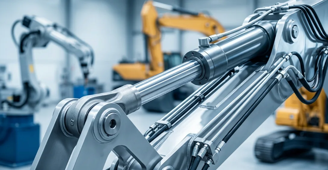
A hydraulic cylinder is a mechanical actuator that converts hydraulic fluid pressure into linear force and motion. It serves as the primary output device in any hydraulic system, translating stored energy into useful work.
Unlike rotary motors that produce spinning motion, hydraulic cylinders generate straight-line push or pull forces. This makes them ideal for lifting, pressing, clamping, and pushing heavy loads with precise control.
The core purpose is force multiplication. A relatively small pump can generate enormous pressure, and when that pressure acts on a piston inside the cylinder barrel, the resulting force can move thousands of tons.
Key Hydraulic Cylinder Components
Every hydraulic cylinder relies on a set of precision-engineered parts working in unison. Understanding these hydraulic cylinder components is essential to grasping how the system operates.
| Component | Function |
|---|---|
| Cylinder Barrel | Houses the piston and contains pressurized fluid |
| Piston | Divides the barrel into two chambers; receives fluid pressure |
| Piston Rod | Transfers linear force from piston to external load |
| Cylinder Head | Seals one end; guides the piston rod movement |
| Cylinder Cap | Seals the opposite end; contains fluid port |
| Seals and O-Rings | Prevent fluid leakage between chambers |
| Hydraulic Fluid Port | Entry and exit point for pressurized hydraulic fluid |
The cylinder barrel is typically made from honed steel tubing with a mirror-smooth interior finish. This surface quality minimizes friction and extends seal life during piston rod movement.
Seals are arguably the most critical wear component. They maintain the pressure differential between chambers that makes force generation possible.
How Does a Hydraulic Cylinder Work — Step-by-Step
The Role of Hydraulic Fluid Pressure
The entire operation of a hydraulic cylinder rests on Pascal's Law. This principle states that pressure applied to a confined fluid transmits equally in all directions throughout that fluid.
In practical terms, this means a pump generating 3,000 PSI delivers that same 3,000 PSI to every square inch of the piston face inside the cylinder. The fluid acts as a rigid force transmitter while remaining flexible enough to flow through hoses and fittings.
This is what enables force multiplication. A small-diameter pump piston working at high pressure can drive a large-diameter cylinder piston to produce enormous output force.
Extension Stroke (Outstroke)
During the extension stroke, hydraulic fluid enters the cap-side chamber through the fluid port. As pressurized fluid fills this chamber, it pushes against the full face of the piston.
The piston moves forward, extending the piston rod outward through the cylinder head. This outward piston rod movement performs useful work on the connected load, whether lifting a boom, pressing a die, or pushing a gate.
Simultaneously, fluid on the rod side of the piston is displaced and flows back to the reservoir through the return line. The speed of extension depends on how quickly fluid enters the cap-side chamber.
Retraction Stroke (Instroke)
Retraction reverses the process. The directional control valve shifts, routing pressurized hydraulic fluid into the rod-side chamber instead.
Fluid pushes against the annular area of the piston (full piston area minus the rod cross-section), driving the piston backward. The rod retracts into the cylinder barrel.
Because the annular area is smaller than the full piston area, retraction produces less force but higher speed at the same flow rate. Exhausted fluid from the cap side returns to the reservoir for recirculation.
Force and Speed Relationship
The performance of any hydraulic cylinder comes down to the relationship between pressure, area, flow rate, and speed. These formulas govern every design decision.
| Parameter | Formula | Influencing Factor |
|---|---|---|
| Force Output | F = P × A | Fluid pressure × piston area |
| Extension Speed | v = Q / A (cap side) | Flow rate ÷ piston area |
| Retraction Speed | v = Q / A (rod side) | Flow rate ÷ annular area |
| Power | P = F × v | Force × velocity |
Notice the inverse relationship between force and speed. A larger piston area generates more force but moves slower at a given flow rate. Engineers balance these parameters based on application requirements.
Power remains constant in an ideal system. You can trade force for speed or speed for force, but you cannot increase both without adding more input power from the pump.
Types of Hydraulic Cylinders by Operation
Single Acting Cylinder
A single acting cylinder receives hydraulic fluid pressure on one side of the piston only. The return stroke relies on an external force, typically gravity or a built-in spring.
This design simplifies the hydraulic system mechanism because only one fluid line is needed. However, it limits control over the return stroke speed and force.
Single acting cylinders are common in hydraulic jacks, dump truck hoists, and simple lift applications where gravity naturally handles retraction.
Double Acting Cylinder
The double acting cylinder is the workhorse of industrial hydraulics. It receives pressurized fluid on both sides of the piston, providing powered control in both extension and retraction.
This gives operators precise command over piston rod movement in both directions. Force, speed, and position can be controlled throughout the entire stroke length.
Double acting cylinders dominate applications where loads must be pushed and pulled with equal authority, from excavator arms to manufacturing presses and steering systems.
Telescopic Cylinder
Telescopic cylinders contain multiple nested stages that extend sequentially. Each stage slides within the next larger stage, achieving long stroke lengths from a compact retracted package.
They can be single acting or double acting, though single acting designs are more common due to the complexity of routing fluid to multiple stages. The outermost stage extends first, followed by progressively smaller inner stages.
You find telescopic cylinders in dump truck bodies, aerial work platforms, and any application requiring long reach from limited mounting space.
Comparison Table
| Type | Powered Directions | Complexity | Common Application |
|---|---|---|---|
| Single Acting | One | Low | Hydraulic jacks, dump trucks |
| Double Acting | Two | Medium | Excavators, presses, cranes |
| Telescopic | One or Two | High | Dump bodies, aerial platforms |
Choosing the right type depends on your force requirements, available mounting space, and whether you need controlled motion in both directions. The double acting cylinder remains the default choice for most industrial hydraulic system mechanism designs.
The Complete Hydraulic System Mechanism
System Components Working Together
A hydraulic cylinder never works in isolation. It operates within a complete hydraulic system mechanism where each component plays a defined role in the energy transfer chain.
The sequence flows as follows: reservoir stores fluid, the pump pressurizes it, control valves direct it, the hydraulic cylinder converts it to mechanical force, and return lines bring spent fluid back to the reservoir.
The reservoir also serves as a heat sink and settling tank where air bubbles separate and contaminants settle. Pump selection determines the maximum flow rate and pressure available to the cylinder.
Control Valves and Flow Regulation
Three categories of valves govern hydraulic cylinder operation. Directional control valves determine which chamber receives fluid, controlling whether the piston rod extends or retracts.
Pressure control valves set maximum system pressure and protect components from overload. Relief valves open when pressure exceeds safe limits, diverting flow back to the reservoir.
Flow control valves regulate the volume of fluid reaching the cylinder per unit time. This directly controls piston rod movement speed, enabling precise positioning and smooth operation under varying loads.
Heat Dissipation and Fluid Conditioning
Every hydraulic system generates heat through fluid friction, pressure drops across valves, and internal leakage. Excessive heat degrades hydraulic fluid, accelerates seal wear, and reduces system efficiency.
Oil coolers, typically air-to-oil or water-to-oil heat exchangers, maintain fluid temperature within optimal operating ranges. Most systems target fluid temperatures between 100°F and 140°F for peak performance.
Filtration removes particulate contamination that would otherwise score cylinder bores and damage seals. Clean hydraulic fluid pressure transmission depends on maintaining fluid cleanliness to ISO 4406 standards.
Real-World Applications and Performance Data
Hydraulic cylinders serve virtually every industry that requires controlled linear force. The operating pressures and cylinder types vary based on application demands.
| Industry | Application | Typical Pressure (PSI) | Cylinder Type |
|---|---|---|---|
| Construction | Excavator arms | 3,000–5,000 | Double acting cylinder |
| Manufacturing | Metal stamping press | 5,000–10,000 | Double acting |
| Agriculture | Tractor loaders | 2,500–3,500 | Double acting |
| Aerospace | Landing gear actuation | 3,000–5,000 | Single/Double acting |
| Waste Management | Compactor trucks | 2,000–3,000 | Telescopic |
Construction equipment typically operates in the 3,000 to 5,000 PSI range, balancing force output with component weight. Manufacturing presses push higher because stationary installations can accommodate heavier, stronger hydraulic cylinder components.
Aerospace applications demand the highest reliability standards. Landing gear cylinders must perform flawlessly after sitting idle for hours, then actuating under extreme loads during landing.
Maintenance and Operational Efficiency
Common Failure Points
Seal degradation is the number one cause of hydraulic cylinder failure. Seals harden, crack, or wear over time, allowing internal leakage that reduces force output and wastes energy.
Rod scoring creates pathways for external leakage. Even microscopic scratches on the piston rod surface can destroy lip seals and allow contamination to enter the cylinder barrel.
Fluid contamination accelerates all other failure modes. Particles as small as 5 microns can damage precision-finished surfaces inside hydraulic cylinder components, creating a cascade of wear.
Preventive Maintenance Checklist
Proactive maintenance extends cylinder life dramatically and prevents costly unplanned downtime. Follow these intervals for optimal performance.
- Fluid analysis: Test hydraulic fluid every 500 operating hours for contamination, viscosity, and additive depletion
- Seal inspection: Check for external leakage at rod seals every 250 hours; replace seals at first sign of weeping
- Rod surface care: Inspect piston rod for scratches, pitting, or corrosion weekly; protect exposed rods during storage
- Pressure testing: Verify cylinder holds rated pressure without drift every 1,000 hours to detect internal leakage early
- Mounting hardware: Check pins, clevises, and mounting bolts for wear and proper torque monthly
- Filter replacement: Change hydraulic filters per manufacturer schedule or when differential pressure indicators trigger
Consistent maintenance keeps hydraulic fluid pressure stable and predictable. A well-maintained cylinder can operate for 10,000+ hours before requiring a rebuild.
Frequently Asked Questions (FAQ)
What makes a hydraulic cylinder extend and retract?
Pressurized hydraulic fluid enters one chamber, pushing the piston and rod outward (extension) or inward (retraction), following Pascal's Law of fluid pressure transmission. A directional control valve determines which chamber receives pressurized fluid at any given moment, controlling the direction of piston rod movement.
What is the difference between single acting and double acting cylinder?
A single acting cylinder uses hydraulic fluid pressure on one side only, relying on gravity or a spring for the return stroke. A double acting cylinder receives pressurized fluid on both sides of the piston, providing powered and controlled movement in both extension and retraction directions.
How is hydraulic cylinder force calculated?
Force equals hydraulic fluid pressure multiplied by the piston area (F = P × A). For example, 3,000 PSI acting on a 4-inch diameter piston (12.57 square inches) produces 37,710 pounds of force. Increasing either pressure or piston diameter raises output force proportionally.
What causes a hydraulic cylinder to fail?
The most common causes are seal wear from age or contamination, scored piston rods from debris or side loading, contaminated hydraulic fluid introducing abrasive particles, and exceeding rated pressure limits. Regular maintenance of hydraulic cylinder components prevents most failures.
How does hydraulic fluid pressure affect cylinder speed?
Speed depends on flow rate divided by piston area, not pressure directly. Higher flow rate from the pump increases piston rod movement speed, while a larger piston area decreases speed at the same flow rate. Pressure determines force capacity, while flow rate determines velocity.
Where are double acting cylinders most commonly used?
Double acting cylinders dominate construction equipment like excavators and cranes, manufacturing presses, agricultural machinery, and mobile hydraulic applications. Any hydraulic system mechanism requiring controlled force in both push and pull directions benefits from the double acting cylinder design.



