
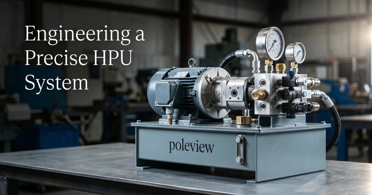
Sizing a hydraulic power unit is where physics, economics, and field reality collide. Get the pressure and flow calculations right but botch the reservoir thermal balance, and you'll cook the fluid within a shift. Nail every component in isolation but ignore duty cycle, and the motor trips on overload before the warranty expires.
This guide walks through the engineering discipline of HPU sizing from first principles, translating governing equations into pump, motor, reservoir, and fluid specifications. Every table and worked example is drawn from the same calculation methods used in industrial press design, mobile equipment, and precision servo systems.
1. Fundamentals of Hydraulic Power Unit Sizing
Before selecting a single component, an engineer needs a shared vocabulary and a clear mental model of what an HPU actually does. Sizing decisions cascade: a wrong pressure class forces a wrong pump class, which forces a wrong motor, which forces a wrong thermal design.
1.1 What an HPU Actually Delivers: Pressure vs. Flow vs. Power
Hydraulic systems don't deliver "power" as a single quantity. They deliver two independent variables: pressure, which is set by the load resisting the actuator, and flow, which is set by the speed at which the actuator must move.
Their product is hydraulic power. The core equation used throughout every hydraulic power pack sizing exercise is:
P (kW) = (Q × p) / 600, where Q is flow in L/min and p is pressure in bar.
A 60 L/min pump running at 200 bar delivers 20 kW of hydraulic power. That same 20 kW could equally come from 20 L/min at 600 bar. Which combination you choose has profound implications for component cost, safety class, and thermal load.
1.2 The Five-Variable Sizing Framework
Every hydraulic system design decision reduces to five interdependent variables. Skip any one and you're guessing.
- Actuator load — the peak and continuous forces the system must overcome, driving pressure requirements.
- Cycle time — the required actuator velocity, driving flow requirements.
- Duty cycle — the percentage of time the system operates at load, driving motor rating and thermal design.
- Ambient conditions — temperature range, altitude, and contamination class, driving fluid and cooling choices.
- Mounting envelope — physical space, weight, and noise limits, constraining reservoir and prime mover selection.
1.3 Common Sizing Mistakes That Compound Downstream
Field service data consistently points to the same handful of errors. Oversizing the pump to "future-proof" the system inflates every downstream component and wastes energy on every cycle. Undersizing the reservoir to save panel space forces active cooling that would otherwise be unnecessary.
Ignoring intermittent duty when selecting the motor leads to nuisance overload trips or, worse, quiet insulation degradation that shortens service life by years. Each of these mistakes is cheap to avoid on paper and expensive to correct in the field.
2. Defining System Requirements Before Any Calculation
The pre-calculation phase is where poor input data becomes poor hardware. Manufacturer field data suggests that skipping requirements definition is the leading cause of HPU replacement within 18 months of commissioning.
2.1 Cataloging Actuator Loads and Motion Profiles
Build a load table for every cylinder and hydraulic motor in the system. For cylinders, capture bore, rod diameter, stroke, stall force, running force, and return-stroke differentials. Single-rod cylinders have asymmetric areas, and the return stroke can demand up to twice the flow at half the force.
For hydraulic motors, document displacement, required torque, and rotational speed under both starting and continuous conditions. Starting torque routinely runs 20–40% above steady-state torque.
2.2 Establishing Duty Cycle and Simultaneity Factors
Determine whether actuators operate sequentially or simultaneously. A machine with six cylinders that never fire together needs far less flow than one where three fire at once. Apply a simultaneity coefficient (typically 0.6–1.0) to the summed peak flow demand.
Duty cycle classification also determines the motor service rating. An S3 intermittent-duty motor is significantly cheaper than an equivalent S1 continuous-duty motor and often more appropriate.
2.3 Environmental and Installation Constraints
Ambient temperature range dictates fluid viscosity grade and cooler sizing. Altitude derates both the motor (roughly 1% per 100 m above 1000 m) and the cooling capacity of air-based heat exchangers. IP rating, footprint limits, and noise ceilings (often ≤75 dB(A) for indoor industrial installations) round out the constraint set.
Table 1: Typical Duty Cycle Classifications
| Duty Class | Load Factor | Time On/Off | Typical Application |
|---|---|---|---|
| Continuous (S1) | 100% | Always on | Test rigs, extrusion |
| Intermittent (S3) | 40–60% | 10 min cycle | Presses, injection molding |
| Short-time (S2) | 25% | ≤30 min run | Mobile equipment, lifts |
| Standby with peaks | <20% | Rare peaks | Emergency systems, clamping |
3. System Operating Pressure Requirements
Pressure sizing sets the mechanical class of every downstream component. It directly influences cost, weight, safety margins, and the pressure certification required for the entire assembly.
3.1 Calculating Working Pressure from Actuator Loads
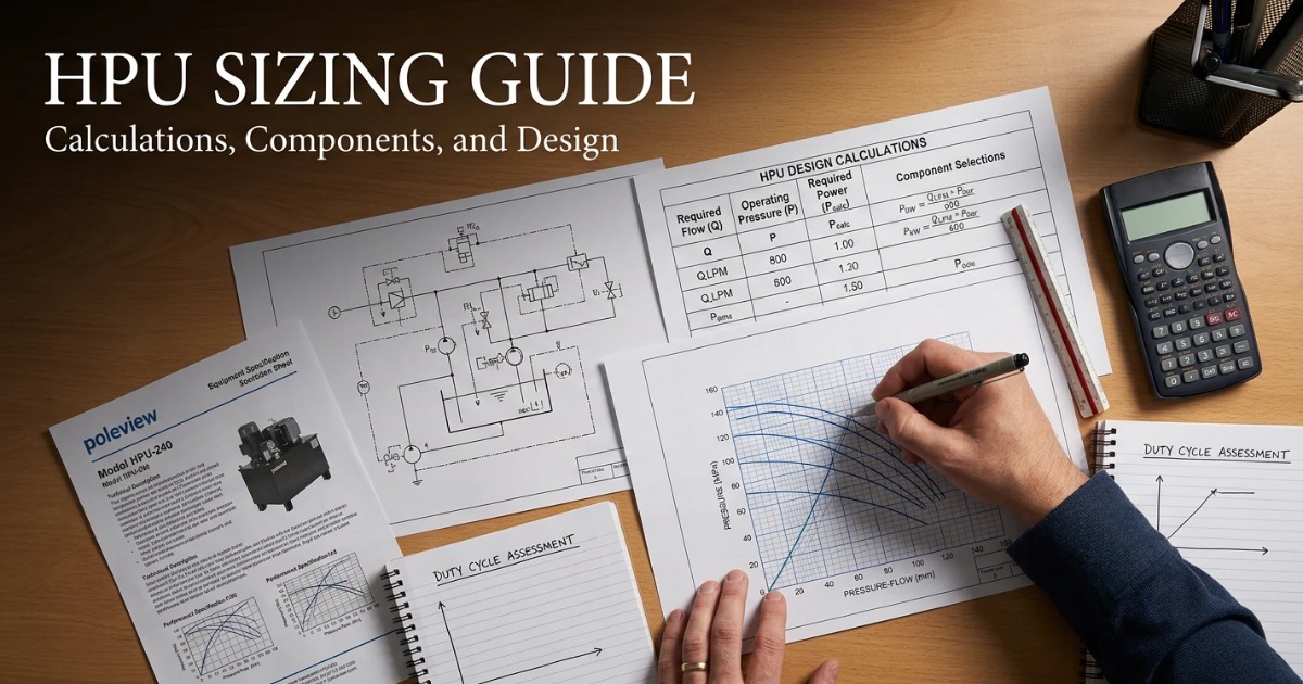
Working pressure derives from the fundamental relationship p = F / A. For a 100 mm bore cylinder generating 50 kN of force, the required pressure is 50,000 N divided by 7854 mm², or about 63.7 bar.
To that, add pressure drops across directional valves, filters, and line losses. These typically account for 8–15% of working pressure and must be included before selecting a pressure class.
3.2 Selecting Maximum System Pressure and Safety Factor
Add a 20–30% margin above working pressure for the relief valve setting. This margin absorbs transient spikes without dumping fluid across the relief on every high-load cycle.
Then match the total to a standard pressure class. Selecting a non-standard rating forces custom components and inflates cost with no engineering benefit.
3.3 Pressure Class Selection Reference
Table 2: Standard Pressure Classes and Application Fit
| Class | Working Pressure | Typical Use | Component Cost Index |
|---|---|---|---|
| Low | ≤70 bar | Mobile utility, agriculture | 1.0 |
| Medium | 70–160 bar | General industrial | 1.4 |
| High | 160–250 bar | Presses, injection molding | 1.8 |
| Very High | 250–350 bar | Heavy forging, marine | 2.6 |
| Ultra High | >350 bar | Aerospace test, subsea | 4.0+ |
4. Pump Flow Rate Selection and Sizing
Flow sizing determines actuator speed and, combined with pressure, sets the required prime mover power. Hydraulic pump sizing calculation is where most sizing spreadsheets earn their keep.
4.1 Calculating Required Flow from Actuator Speed
For cylinders, flow demand follows Q = (A × v × 60) / 1000, where A is piston area in cm² and v is velocity in m/s, yielding Q in L/min. For hydraulic motors, use Q = (D × n) / 1000, where D is displacement in cm³/rev and n is speed in rpm.
Differential-area corrections matter for single-rod cylinders. When rod-side is pressurized, the effective area is smaller and velocity for a given flow rises accordingly. Design for the demanding side of the cycle.
4.2 Accounting for Volumetric Efficiency and Leakage
Rated pump displacement isn't delivered flow. Volumetric efficiency captures internal leakage that increases with pressure and decreases with fluid viscosity.
- External gear pumps: 0.88–0.93
- Vane pumps (balanced): 0.90–0.95
- Axial piston pumps: 0.92–0.97
Divide the required flow by the efficiency figure before specifying displacement. A pump delivering 40 L/min at 200 bar with 0.92 efficiency needs about 43.5 L/min of theoretical displacement.
4.3 Choosing Pump Type: Gear, Vane, or Piston
Selection depends on pressure class, cycle profile, contamination tolerance, and cost. Fixed-displacement pumps are simpler and cheaper. Variable-displacement pumps deliver only the flow needed at any instant, which slashes energy consumption on partial-load duty.
Table 3: Pump Type Selection Matrix
| Pump Type | Max Pressure | Volumetric η | Noise Level | Contamination Tolerance | Best For |
|---|---|---|---|---|---|
| External Gear | 250 bar | 0.88–0.93 | High | Excellent | Simple, cost-driven systems |
| Vane (balanced) | 175 bar | 0.90–0.95 | Low | Good | Machine tools, quiet ops |
| Axial Piston (fixed) | 350 bar | 0.94–0.97 | Medium | Fair | High-pressure continuous |
| Axial Piston (variable) | 420 bar | 0.92–0.96 | Medium | Fair | Variable-load, energy-critical |
4.4 Handling Peak vs. Continuous Flow with Accumulators
If the flow profile is spiky, an accumulator can supply peak demand while the pump sizes to average flow. For a system that draws 100 L/min for 2 seconds every 30 seconds, a 20 L/min pump plus accumulator often replaces a 100 L/min pump.
Gas pre-charge pressure should be set at roughly 0.9 × the minimum working pressure to maximize usable volume without shortening bladder life.
5. Electric Motor Horsepower Requirements
Prime mover sizing must reconcile hydraulic power demand, pump efficiency, service factor, and thermal limits. Undersize it and the motor overheats. Oversize it and you pay for capacity that's never used while stressing the pump drive shaft.
5.1 Calculating Required Motor Power
The complete motor sizing equation folds in both hydraulic-to-mechanical losses in the pump and mechanical losses in the coupling:
P_motor (kW) = (Q × p) / (600 × η_pump × η_mech)
Overall efficiency for a well-matched pump-motor assembly typically falls between 0.80 and 0.88. Anything below 0.75 suggests a mismatched pump, and anything above 0.90 suggests optimistic bench data that won't hold up in the field.
5.2 Service Factor and Starting Torque Considerations
Cyclical loads warrant a 10–25% service factor over the calculated steady-state power. This margin absorbs cold-start viscosity spikes, transient pressure peaks, and drift in operating conditions over the equipment lifetime.
Starting torque is a separate check. On a cold morning with VG 68 fluid at 0 °C, viscosity can exceed 1000 cSt and drag the pump shaft hard. Verify that the motor's locked-rotor and pull-up torque comfortably clear the cold-start load.
5.3 Matching Motor to Pump Speed and Frame Size
Standard 4-pole motors (1450 rpm at 50 Hz, 1750 rpm at 60 Hz) are the industrial default and best match to typical pump displacement ranges. Consider 2-pole motors when compactness matters more than noise, and 6-pole when quiet operation is critical and the extra frame size is acceptable.
Table 4: Motor-Pump Power Correlation at 175 bar
| Flow Rate (L/min) | Hydraulic Power (kW) | Motor Power at 85% η (kW) | Standard IEC Motor (kW) |
|---|---|---|---|
| 10 | 2.9 | 3.4 | 4.0 |
| 20 | 5.8 | 6.9 | 7.5 |
| 40 | 11.7 | 13.7 | 15.0 |
| 75 | 21.9 | 25.7 | 30.0 |
| 150 | 43.8 | 51.5 | 55.0 |
5.4 Variable Frequency Drives and Energy Recovery
VFDs paired with fixed-displacement pumps often outperform variable-displacement systems on intermittent duty. Energy savings of 30–50% are routinely reported in industry case studies published through 2025, particularly on injection molding and press applications where flow demand varies sharply within each cycle.
The trade-off is drive cost and harmonic mitigation. Below 15 kW, the payback often stretches past three years unless duty cycle is highly variable.
6. Hydraulic Reservoir Capacity Calculation
Hydraulic reservoir sizing balances thermal capacity, air separation, contamination settling, and physical footprint. Reservoir sizing rules of thumb are useful shortcuts but fail in specific applications where thermal or dwell requirements dominate.
6.1 The 3-to-5 Rule and Its Limitations
The traditional guideline sizes reservoir volume at 3× to 5× the pump flow rate per minute. A 40 L/min pump gets a 120–200 L reservoir. This works well for stationary industrial systems at moderate duty.
It fails on high-power-density mobile HPUs where space is scarce and active cooling is mandatory anyway. It also fails on closed-circuit systems, where the reservoir handles only case drain and thermal expansion rather than the full circulating flow.
6.2 Thermal-Based Reservoir Sizing
When natural convection off the reservoir surface must dissipate meaningful heat, calculate required surface area directly:
A_reservoir = Q_heat / (k × ΔT), where k is the heat transfer coefficient (typically 12–15 W/m²·K for still air) and ΔT is the difference between fluid and ambient temperature.
For a 3 kW heat load with a 30 °C temperature differential, the required surface area is roughly 7–8 m². That's a physically large reservoir, which is precisely why active cooling takes over above this threshold.
6.3 Air Separation and Dwell Time Requirements
Fluid entering the reservoir carries entrained air that must separate before returning to the pump. Minimum dwell time of 3–5 minutes serves standard applications. Precision servo systems and aviation hydraulics extend this to 8–10 minutes to eliminate compressibility artifacts in control response.
Dwell time equals reservoir volume divided by return flow rate. A 200 L reservoir with 40 L/min return provides 5 minutes.
6.4 Reservoir Geometry and Internal Baffling
Length-to-width ratios of 2:1 or 3:1 promote laminar flow between return and suction. A baffle between the two ports forces returning fluid to travel the long way around, giving air time to rise and contamination time to settle.
Maintain a minimum fluid level of at least 100 mm above the suction strainer under all conditions, including cylinder extension. Air ingestion at the suction is one of the most damaging conditions a pump can experience.
Table 5: Reservoir Sizing Comparison by Application
| Application | Sizing Rule | Example: 40 L/min Pump | Cooling Strategy |
|---|---|---|---|
| Stationary industrial | 3–5× flow | 120–200 L | Reservoir surface + fan |
| Mobile equipment | 1–1.5× flow | 40–60 L | Air-oil or water cooler |
| Servo/precision | 5–8× flow | 200–320 L | Dedicated chiller |
| Continuous high-power | Thermal-calc based | Varies | Forced heat exchanger |
7. Hydraulic Fluid Viscosity Considerations
Fluid selection influences efficiency, wear, cold-start behavior, and thermal stability across the operating envelope. The wrong grade can turn a well-sized HPU into a maintenance liability.
7.1 Viscosity Grades and Operating Temperature Windows
ISO VG grades number the fluid's kinematic viscosity in cSt at 40 °C. VG 46 measures 46 cSt at 40 °C. As temperature rises, viscosity drops sharply and internal leakage climbs.
The optimal viscosity at the pump inlet is 16–36 cSt for most pump types. Match the grade to the expected operating temperature so the fluid lives in that band during normal running, not just at startup.
7.2 Viscosity Index and Multi-Grade Fluids
Viscosity index (VI) measures how much viscosity changes with temperature. Standard mineral oils sit around VI 100. High-VI fluids (>140) resist thinning at high temperature and thickening at low temperature.
The premium is typically 30–60% over standard fluid. It pays back in outdoor mobile equipment operating across wide temperature swings but rarely in temperature-controlled indoor installations.
7.3 Fluid Compatibility with System Materials
Seal materials must match fluid chemistry. NBR (nitrile) is the default for mineral oils. FKM (Viton) handles higher temperatures and synthetic fluids. EPDM is required for phosphate-ester fire-resistant fluids and is incompatible with mineral oils.
Phosphate esters also attack certain copper alloys, so any brass or bronze components in valves and fittings need verification. Biodegradable fluids (HEES, HETG) have their own compatibility matrices and are essential for environmentally sensitive installations near waterways.
Table 6: ISO Viscosity Grade Selection Guide
| Ambient Range | Recommended ISO Grade | Cold-Start Viscosity Max | Typical Operating Temp |
|---|---|---|---|
| −20 to +10 °C | VG 32 | 800 cSt | 30–50 °C |
| 0 to +30 °C | VG 46 | 1000 cSt | 40–60 °C |
| +10 to +40 °C | VG 68 | 1200 cSt | 50–70 °C |
| +20 to +50 °C | VG 100 | 1500 cSt | 60–80 °C |
8. Thermal Management and Cooling Sizing
Heat rejection is the most frequently underestimated sizing task. Undersized cooling shortens fluid and component life dramatically, and it usually shows up only after commissioning when the fluid temperature climbs past 65 °C and refuses to plateau.
8.1 Calculating Heat Load from System Inefficiency
Every watt of input power that isn't converted to useful actuator work becomes heat. The calculation is direct:
Q_heat = P_input × (1 − η_overall)
An 85% efficient 30 kW system generates 4.5 kW of continuous heat. That's roughly the output of two space heaters running nonstop. If the reservoir and lines can't shed that much through natural convection, temperature rises until fluid degradation accelerates.
8.2 Reservoir vs. Active Cooling Threshold
Natural reservoir dissipation covers heat loads up to roughly 3–5 kW on typical industrial reservoirs. Above that, plan on active cooling from the start. Retrofit coolers are almost always more expensive and less integrated than coolers specified during initial design.
Air-oil coolers suit installations with clean, cool ambient air. Water-oil coolers deliver higher heat transfer density but require a water supply and add fouling as a maintenance concern.
8.3 Sizing Heat Exchangers
Heat exchanger selection depends on ΔT between oil and cooling medium and on required duty. Add 20–30% capacity margin for filter fouling, ambient extremes, and gradual heat exchanger degradation.
Oversizing the cooler modestly is far cheaper than adding one later. Undersizing by even 10% often means the system never reaches steady-state temperature on hot days.
9. Filtration and Contamination Control Sizing
Cleanliness targets drive filter placement and flow ratings. Roughly 70–80% of hydraulic component failures trace back to contamination, so filter sizing directly determines component lifespan.
9.1 Target ISO 4406 Cleanliness Codes by System Type
Servo and proportional systems require ISO 4406 codes of 16/14/11 or cleaner. Standard industrial systems tolerate 20/18/15. Each numeric step cleaner requires roughly a β-ratio order of magnitude improvement in filter performance.
9.2 Sizing Suction, Pressure, and Return Filters
Filter flow capacity should be 2–3× nominal pump flow. This margin accommodates cold-start viscosity, pressure spikes, and gradual element loading without kicking the bypass valve open. A bypassing filter is a filter that isn't filtering.
Return filters catch wear debris before it re-enters the reservoir. Pressure filters protect downstream servo valves. Suction strainers protect the pump from large particles but shouldn't be relied on for fine filtration.
10. Worked Example: Sizing an HPU for a 50-Ton Hydraulic Press
Applied end-to-end to a real application, the calculations above produce a concrete BOM in under an hour.
10.1 Requirements Definition
- Force: 50 tons (490 kN)
- Cylinder: 100 mm bore, single rod
- Stroke: 500 mm
- Cycle time: 8 seconds working stroke
- Frequency: 20 cycles per hour
- Ambient: 25 °C indoor
10.2 Pressure, Flow, and Power Calculations
Working pressure: Piston area = π × (100/2)² = 7854 mm². Pressure = 490,000 N / 7854 mm² = 62.4 bar. Adding 15% for valve and line losses gives 71.8 bar working pressure. Round up to a 100 bar system pressure class with relief set at 90 bar.
Required flow: Stroke velocity = 500 mm / 8 s = 62.5 mm/s. Flow = 78.54 cm² × 6.25 cm/s × 60 / 1000 = 29.5 L/min. Applying 0.92 volumetric efficiency yields a theoretical pump displacement of 32 L/min at 1450 rpm, so a 22 cc/rev gear pump fits.
Hydraulic power: P = (29.5 × 71.8) / 600 = 3.5 kW. Applying an 82% overall efficiency and 15% service factor gives 4.9 kW motor demand. The standard 5.5 kW IE3 motor is the natural fit.
10.3 Component Selection Summary
- Pump: 22 cc/rev external gear, 100 bar rated
- Motor: 5.5 kW, 4-pole IE3, IP55
- Reservoir: 100 L (roughly 3× pump flow, adequate for 20 cycles/hour duty)
- Fluid: ISO VG 46 mineral hydraulic oil
- Cooling: No active cooler required; reservoir surface handles the estimated 0.9 kW heat load
- Filtration: 10 μm return filter sized at 3× pump flow, 25/23/20 → 20/18/15 target cleanliness
11. Verification, Commissioning, and Iterative Refinement
Sizing does not end at the drawing. Commissioning data validates or corrects every assumption made during design, and the best design teams treat that feedback loop as mandatory rather than optional.
11.1 Commissioning Measurements That Confirm Sizing
Capture the key data points during initial runs and after 100 hours of operation:
- Steady-state fluid temperature at full duty
- Pump case drain flow (rising trend indicates wear)
- Motor amp draw versus nameplate at peak load
- Pressure ripple at pump outlet
- Filter differential pressure at operating temperature
11.2 When to Resize vs. Retrofit
If the fluid temperature stabilizes 10 °C above target, adding a modest air-oil cooler usually resolves the problem without replacing anything upstream. If motor amp draw runs consistently at 95%+ of nameplate on steady duty, the motor is undersized and should be upgraded rather than run to failure.
Systematic pump wear points to contamination or fluid viscosity issues, not necessarily to a sizing error. Diagnose the root cause before ordering hardware.
12. Frequently Asked Questions
How do I size an HPU when actuator loads are unknown?
Use conservative load estimates (typically 1.5× expected peak) and specify a variable-displacement pump so the system can absorb uncertainty without energy waste at partial load. Building in a metered test point for pressure and flow during commissioning lets you refine the sizing once real data arrives.
Can I use a larger motor than calculated to add safety margin?
Modest oversizing (10–25%) is standard practice and covers service factor. Beyond 25%, oversizing wastes energy, increases starting current and inrush kVA, and can damage the pump if drive torque exceeds shaft ratings during startup. Bigger is not automatically safer.
What is the minimum reservoir size I can specify?
Mobile applications sometimes run reservoirs as small as 0.5× pump flow per minute, but only with active cooling and careful attention to air separation and suction line design. Stationary systems that undersize the reservoir routinely suffer premature fluid oxidation and pump cavitation. Do not undersize without deliberately compensating.
How does altitude affect HPU sizing?
Motor output typically derates about 1% per 100 m above 1000 m elevation. Air-based cooling capacity drops with reduced air density, so heat exchangers need upsizing. NPSH available at the pump suction also falls, which can force a shorter or larger-diameter suction line at high altitude.
Should I size for peak flow or average flow?
Size for peak flow unless an accumulator is specified. Average-flow sizing plus a properly-sized accumulator often reduces motor size by 40–60% on intermittent duty applications. The catch is that accumulator systems require gas pre-charge maintenance and add safety considerations that continuous-flow systems avoid.
How often should HPU sizing be reviewed after installation?
Review sizing at 6 months, 2 years, and whenever the downstream process changes. Load profiles drift as tooling ages, cycle times get pushed, and production requirements evolve. A system that was correctly sized at commissioning can be running 20% over its design point three years later without anyone noticing until a failure occurs.
What software tools help with HPU sizing?
Manufacturer sizing tools from Bosch Rexroth, Parker Hannifin, and Eaton cover component-level selection well and are typically free with an account. For system-level simulation including transient behavior and thermal modeling, Simcenter Amesim and Automation Studio remain the reference platforms. Use manufacturer tools for BOM decisions and simulation platforms for validating dynamic response and thermal balance before hardware commitment.
Do I need to redo sizing calculations if I switch fluid types?
Yes. Switching between mineral oil, phosphate ester, water glycol, or biodegradable fluids changes density, viscosity index, bulk modulus, and seal compatibility. Pump volumetric efficiency and pressure drops shift, and in some cases the pressure class rating of components drops when using fire-resistant fluids. Treat a fluid change as a sizing review, not a drop-in substitution.
How do I account for future capacity expansion in initial sizing?
Design the reservoir and cooling with headroom, since these are the hardest components to upsize later. Specify a pump and motor combination that matches current demand precisely, and plan for pump replacement rather than initial oversizing when capacity growth is anticipated. Motor frames and mounting patterns often accept a range of pump sizes, which makes the upgrade path straightforward without touching the base HPU structure.