

If you've ever worked with hydraulic systems, you know the pump is where it all starts — it's what turns mechanical energy into fluid power. There are plenty of pump designs out there, but one style keeps showing up more than any other, mostly because it's straightforward, tough, and won't break the bank. Once you dig into why that is, the basics of how hydraulic fluid power works start to make a lot more sense.
The selection of a hydraulic pump constitutes a critical engineering decision that fundamentally governs system performance, operational longevity, and total cost of ownership—whether the application involves mobile equipment integration or industrial press design. This technical reference provides a rigorous, comparative analysis of all principal hydraulic pump architectures, evaluating their respective performance characteristics, and presents an evidence-based assessment of the topology that demonstrates superior suitability across the broadest range of hydraulic applications.
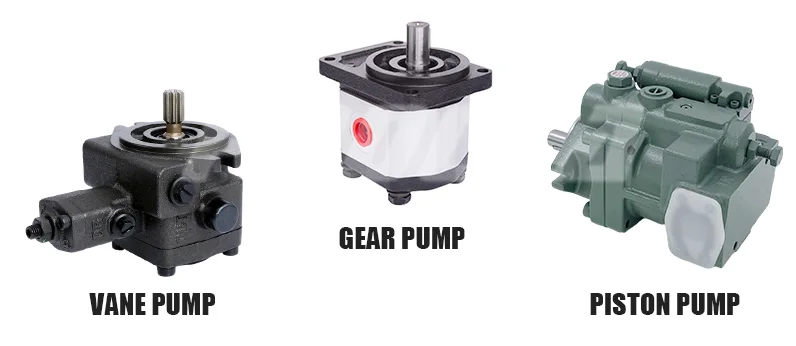
Overview of Hydraulic Pump Types
Hydraulic systems use pumps to create flow that transmits force through confined fluid. The three primary pump categories — gear, vane, and piston — each operate on distinct mechanical principles and serve different segments of the hydraulic fluid power industry.
Choosing the right pump requires understanding how each design converts rotational input into pressurized fluid output. The differences in construction directly affect pressure capability, efficiency, noise, and service life.
Positive Displacement vs. Non-Positive Displacement Pumps
Virtually all hydraulic pump types used in fluid power systems are positive displacement designs. This means they deliver a fixed volume of fluid per revolution, regardless of system pressure.
Non-positive displacement pumps, such as centrifugal designs, cannot maintain flow against high back-pressure. They are suited to high-volume, low-pressure transfer applications like water circulation — not hydraulic power transmission.
Positive displacement is essential because hydraulic systems require consistent flow delivery under varying load conditions. Gear pumps, vane pumps, and piston pumps all fall into this category, making them the only viable choices for hydraulic fluid power circuits.
Key Performance Factors in Pump Selection
Pressure rating determines the maximum load a system can handle. Applications range from 100 bar in light-duty circuits to 700 bar in heavy construction and aerospace.
Flow rate dictates actuator speed. Higher displacement pumps move cylinders and motors faster but require more input power.
Volumetric efficiency measures how much theoretical output the pump actually delivers. Internal leakage reduces efficiency, especially as components wear.
Noise level matters in factory environments and operator-occupied vehicles. Pump geometry directly influences pressure ripple and acoustic output.
Cost and maintenance complexity often drive the final decision. A pump that performs adequately at low acquisition and service cost will beat a technically superior but expensive alternative in most general-purpose systems.
The Gear Pump — The Most Common Hydraulic Pump
The gear pump hydraulic configuration is the industry standard for the majority of systems worldwide. Its dominance stems from an unmatched combination of low cost, mechanical simplicity, and tolerance to real-world operating conditions.
From agricultural tractors to factory conveyor systems, gear pumps handle the bulk of hydraulic fluid power generation. They account for an estimated 50–75% of all hydraulic pumps in service globally.
How External Gear Pumps Work
An external gear pump uses two identical spur gears meshing inside a close-tolerance housing. One gear is driven by the prime mover (typically an electric motor or engine PTO), and it drives the second gear in the opposite direction.
Fluid enters the inlet port and fills the spaces between gear teeth and the housing wall. As the gears rotate, trapped fluid is carried around the outside of each gear from inlet to outlet.
At the mesh point, gear teeth interlock and squeeze fluid out of the spaces, forcing it through the outlet port under pressure. The tight clearances between gear tips and the housing prevent significant backflow, creating the positive displacement action essential to hydraulic pump types.
Internal Gear Pumps and Their Applications
Internal gear pumps use a large external gear (rotor) meshing with a smaller internal gear (idler). A crescent-shaped separator between the two gears creates sealed chambers that carry fluid from inlet to outlet.
Gerotor designs eliminate the crescent seal entirely. They use a specially shaped inner gear with one fewer tooth than the outer gear, creating expanding and contracting chambers as the assembly rotates.
Internal gear pumps produce smoother flow with less pressure pulsation than external designs. They excel in lower-pressure applications like lubrication systems, fuel transfer, and chemical processing where quiet operation and gentle fluid handling matter.
Why Gear Pumps Dominate Most Hydraulic Systems
Simplicity: With only two moving parts (the gears), there is very little that can fail. No complex valve plates, springs, or sliding elements are required.
Durability: Gear pumps tolerate moderate contamination without catastrophic failure. Particles that would score a piston pump's bore simply pass through or embed in softer gear materials.
Affordability: Manufacturing costs are low because gear pumps require fewer precision-machined components. Replacement units are stocked universally.
Compact packaging: The gear pump hydraulic design fits into tight spaces on mobile equipment where weight and envelope size are constrained.
These advantages make gear pumps the default choice unless specific system demands — extreme pressure, variable flow, or ultra-high efficiency — require a more specialized design.
Comparison Table — Hydraulic Pump Types
The following table provides a side-by-side comparison of the three major hydraulic pump types across critical performance metrics. Use this data to evaluate which design fits your system requirements.
| Feature | Gear Pump | Vane Pump | Piston Pump |
|---|---|---|---|
| Typical Pressure Range | Up to 250 bar | Up to 180 bar | Up to 700 bar |
| Volumetric Efficiency | 80–90% | 85–92% | 90–98% |
| Noise Level | Moderate–High | Low–Moderate | Low–Moderate |
| Cost | Low | Medium | High |
| Maintenance Complexity | Low | Medium | High |
| Common Applications | Mobile equipment, industrial machinery | Machine tools, automotive | Aerospace, heavy construction |
| Contamination Tolerance | High | Moderate | Low |
Vane Pump Hydraulic System Applications
The vane pump hydraulic system occupies the middle ground between gear and piston designs. It delivers smoother flow and quieter operation than gear pumps while remaining more affordable than piston pumps.
Vane pumps are the preferred choice when noise reduction and flow quality matter more than maximum pressure capability or contamination tolerance.
Balanced vs. Unbalanced Vane Pump Designs
Unbalanced vane pumps use a single cam ring offset from the rotor center. This creates one suction zone and one pressure zone per revolution. The offset generates a net side load on the rotor shaft, increasing bearing wear over time.
Balanced vane pumps use an elliptical cam ring that creates two suction and two pressure zones per revolution. The opposing pressure zones cancel side loads, dramatically extending bearing and shaft seal life.
Balanced designs dominate industrial vane pump hydraulic system installations because they offer longer service intervals and more predictable maintenance schedules.
Ideal Use Cases for Vane Pumps
Vane pumps excel in stationary industrial applications where consistent pressure and low noise are priorities. Machine tools, injection molding presses, and die-casting equipment commonly use vane pump hydraulic systems.
Automotive power steering systems historically relied on vane pumps for their smooth, quiet output. Their ability to deliver steady flow at moderate pressures (up to 180 bar) makes them well-suited to these applications.
However, vane pumps are less tolerant of contaminated fluid than gear pumps. The sliding vanes require clean oil to maintain their seal against the cam ring, making filtration more critical in vane pump hydraulic system designs.
Piston Pump Hydraulic Applications
The piston pump hydraulic design represents the highest performance tier among hydraulic pump types. When systems demand pressures above 250 bar, variable displacement, or maximum efficiency, piston pumps are the only viable option.
Their complexity and cost are justified in applications where energy savings, precise control, or extreme pressure capability deliver measurable return on investment.
Axial Piston Pumps
Axial piston pumps arrange multiple pistons parallel to the drive shaft inside a rotating cylinder block. A swashplate (angled plate) forces pistons in and out of their bores as the block rotates, creating suction and discharge strokes.
The swashplate angle determines piston stroke length and therefore pump displacement. This is the mechanism that enables variable displacement — adjusting output flow without changing shaft speed.
Axial piston pumps are the most common piston pump hydraulic design, used extensively in construction equipment, aerospace actuators, and high-performance industrial presses.
Radial Piston Pumps
Radial piston pumps position pistons perpendicular to the drive shaft, arranged radially around a central cam or eccentric. As the shaft rotates, the cam pushes pistons outward while spring or pressure return brings them back.
These pumps achieve extremely high pressures (up to 700 bar) and deliver very smooth output flow. They are typically used in steel mill hydraulics, large press systems, and applications requiring sustained high-pressure operation.
Radial designs are less common than axial types due to their larger physical size and higher manufacturing cost. They serve niche applications where their specific advantages are essential.
Variable Displacement Capabilities
Variable displacement is the defining advantage of piston pump hydraulic systems. By adjusting the swashplate angle (axial) or eccentric position (radial), output flow changes continuously from zero to maximum without altering shaft speed.
This capability enables load-sensing systems that match pump output to actual demand, eliminating wasted energy. In mobile equipment, this translates directly to fuel savings and reduced heat generation.
Pressure-compensated piston pumps automatically reduce displacement when system pressure reaches a set limit, protecting components and conserving power. This level of control is impossible with fixed-displacement gear or vane pumps without adding external valving.
Selection Guide Table — Matching Pump Type to System Needs
Use this guide to quickly identify the recommended pump type based on your primary system requirement. Each recommendation reflects the most cost-effective and reliable choice for that application category.
| System Requirement | Recommended Pump Type | Reason |
|---|---|---|
| Low cost, general purpose | Gear pump | Simple, reliable, affordable |
| Low noise, moderate pressure | Vane pump | Smooth flow, quiet operation |
| High pressure, variable flow | Piston pump | Maximum efficiency and control |
| Mobile hydraulics | Gear pump | Compact, contamination tolerant |
| Precision industrial control | Piston pump | Variable displacement accuracy |
Frequently Asked Questions (FAQ)
What type of pump is used in most hydraulic systems?
The gear pump is used in most hydraulic systems due to its low cost, simple construction, high contamination tolerance, and reliable performance across a wide range of applications. Its dominance spans mobile equipment, industrial machinery, and general-purpose hydraulic fluid power circuits where extreme pressure or variable flow are not required.
What is the difference between a gear pump and a piston pump in hydraulic systems?
Gear pumps are simpler and cheaper but operate at lower pressures (up to 250 bar) with 80–90% efficiency. Piston pumps deliver higher pressure (up to 700 bar) and 90–98% efficiency but cost significantly more and require cleaner hydraulic fluid with finer filtration.
Can a vane pump replace a gear pump in a hydraulic system?
In applications requiring lower noise and smoother flow at moderate pressures, a vane pump hydraulic system can replace a gear pump. However, vane pumps cost more, tolerate contamination less effectively, and are limited to approximately 180 bar — making them unsuitable as direct replacements in all scenarios.
Why are gear pumps preferred in mobile hydraulic equipment?
Their compact size, tolerance to contaminated fluid, low maintenance requirements, and affordability make gear pump hydraulic configurations ideal for mobile and field equipment. These environments expose pumps to dirt ingestion, vibration, and irregular maintenance schedules — conditions where gear pumps outperform more sensitive designs.
What hydraulic pump type offers the highest efficiency?
Piston pump hydraulic designs achieve up to 98% volumetric efficiency, making them the top choice for high-performance hydraulic fluid power systems. Their variable displacement capability further improves overall system efficiency by matching output to demand and eliminating energy waste through throttling.



