

The hydraulic gear pump constitutes a fundamental component within marine hydraulic systems, serving as the primary driver for critical shipboard operations including anchor windlass actuation, deck crane manipulation, and steering gear functionality under adverse sea conditions. A comprehensive understanding of this precision-engineered mechanism is essential for ensuring operational reliability and mitigating the risk of unscheduled maintenance interventions and associated vessel downtime.
If you've spent any time working on deck, you know the hydraulic gear pump is what keeps everything running. Winches, steering gear, cargo cranes — they all depend on it. It's a straightforward piece of machinery, really. Takes mechanical energy and turns it into hydraulic pressure, pushing fluid where it needs to go. Nothing glamorous about it, but without one working properly, a ship isn't going anywhere.
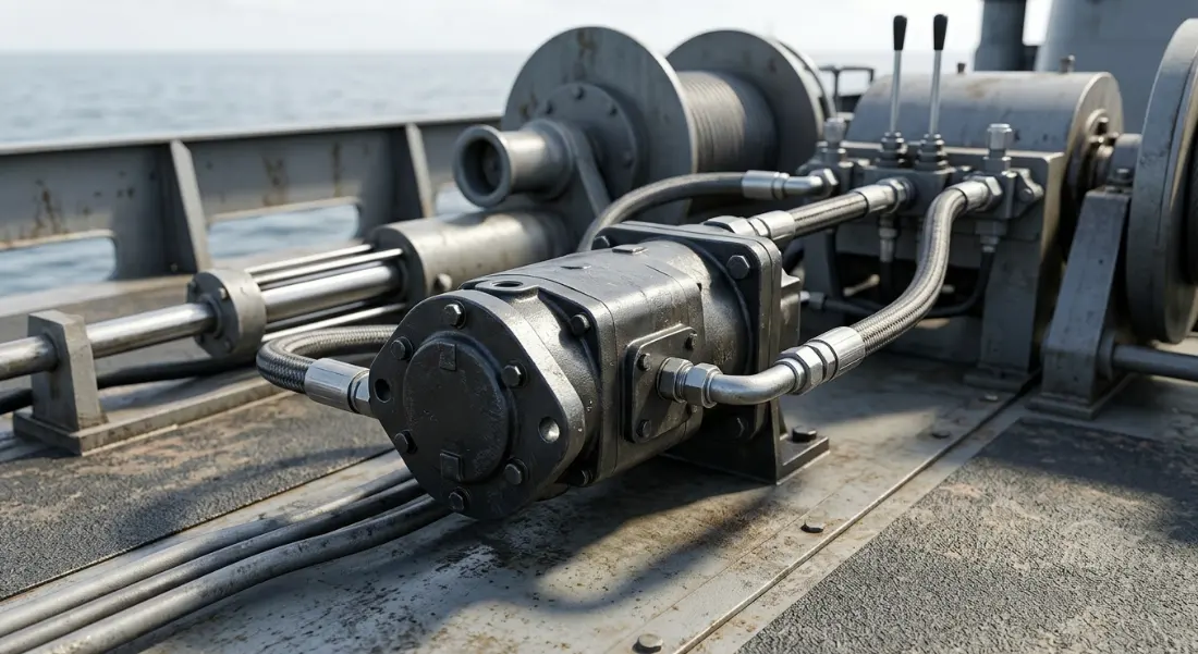
Understanding Hydraulic Gear Pumps in Marine Applications
Definition and Core Function
A hydraulic gear pump is a positive displacement pump that uses the meshing action of rotating gears to move hydraulic fluid under pressure. Within the hydraulic system marine vessel infrastructure, it acts as the primary energy converter — transforming mechanical rotation from an electric motor or diesel engine into pressurized fluid flow.
This pressurized flow is what powers every hydraulic actuator, motor, and cylinder aboard the ship. Without the gear pump generating consistent hydraulic fluid pressure displacement, deck machinery would be inoperable.
The gear pump's role within the marine hydraulic power unit is fundamental. It draws low-pressure oil from a reservoir and delivers it at elevated pressure to the system's directional control valves, which then route fluid to the appropriate equipment.
Why Ships Rely on Gear Pumps Over Other Pump Types
Marine engineers consistently choose gear pumps for ship deck machinery hydraulic circuits because of their inherent simplicity. With only two primary moving parts — the gears themselves — there are fewer components that can fail in the harsh marine environment.
Compared to vane pumps, gear pumps tolerate contaminated oil far better, a significant advantage when maintenance intervals may be extended during long ocean passages. They also handle higher viscosity fluids without performance degradation, which matters in cold-weather operations.
Against piston pumps, gear pumps win on cost-effectiveness and ease of maintenance. While piston pumps deliver higher pressures, most ship deck machinery hydraulic applications operate well within the gear pump's pressure range. The reduced complexity translates directly into lower spare parts inventory and simpler onboard repairs.
Gear Pump Working Principle
Internal Mechanism — How Fluid Moves
The gear pump working principle relies on a straightforward mechanical process. Two gears rotate inside a closely fitted housing — one gear is driven by the prime mover (the drive gear), while the second gear (the idler) meshes with it and rotates in the opposite direction.
As the gear teeth unmesh on the suction side, they create an expanding volume that generates a partial vacuum. This vacuum draws hydraulic fluid from the reservoir into the pump housing through the inlet port.
The fluid is then trapped in the spaces between the gear teeth and the pump casing. As the gears rotate, they carry this trapped fluid around the periphery of the housing from the suction side to the discharge side.
On the discharge side, the gear teeth mesh together again, reducing the volume between them and forcing the fluid out through the outlet port at elevated pressure. This continuous process creates a steady, non-pulsating flow that is ideal for ship deck machinery hydraulic systems.
External vs. Internal Gear Pumps on Ships
Ships employ both external and internal gear pump configurations depending on the application requirements. External gear pumps use two identical spur gears rotating in opposite directions, while internal gear pumps feature a smaller gear rotating inside a larger ring gear.
Each type offers distinct advantages for specific marine hydraulic power unit applications. The choice between them depends on pressure requirements, noise sensitivity, and flow characteristics needed for the particular system.
| Feature | External Gear Pump | Internal Gear Pump |
|---|---|---|
| Gear Arrangement | Two identical gears | One gear inside another |
| Pressure Range | Up to 250 bar | Up to 170 bar |
| Flow Rate | Higher | Moderate |
| Noise Level | Higher | Lower |
| Common Ship Use | Deck cranes, winches | Steering gear, hatch covers |
External gear pumps dominate high-pressure, high-flow applications like deck cranes and anchor windlasses. Their robust construction handles the demanding load cycles of cargo operations without premature wear.
Internal gear pumps excel in applications where smooth, quiet operation is prioritized. Steering gear systems benefit from their low-pulsation output, which provides precise rudder control without hydraulic hammer effects in the piping.
Key Components of a Marine Hydraulic Gear Pump
Gears, Casing, Bearings, and Seals
The gears are the primary working elements, precision-machined to maintain tight tolerances that minimize internal leakage. In a marine hydraulic power unit, gear tooth profiles are carefully designed to optimize fluid displacement while reducing trapped pressure between meshing teeth.
The pump casing (or body) houses the gears and provides the sealed chamber where pressure develops. It must withstand continuous operating pressures while maintaining dimensional stability under thermal cycling common in engine rooms.
Bearings support the gear shafts and maintain precise alignment under load. Marine gear pumps typically use journal bearings or needle roller bearings rated for the side-loading forces generated by pressure differentials across the gears.
Shaft seals prevent external leakage where the drive shaft exits the pump body. These seals must handle the pressure differential between the pump interior and the atmosphere while accommodating shaft rotation speeds up to 3,000 RPM.
Materials Used for Marine-Grade Durability
Marine gear pumps face a uniquely hostile environment combining saltwater exposure, humidity, vibration, and temperature extremes. Material selection directly determines service life in these conditions.
Gear teeth are typically manufactured from case-hardened alloy steel, providing a hard wear surface over a tough, shock-resistant core. Surface hardness values of 58–62 HRC are standard for gears operating in ship deck machinery hydraulic systems.
Pump casings are commonly cast from high-grade iron or aluminum alloys with protective surface treatments. For vessels operating in extreme environments, stainless steel or bronze housings provide superior corrosion resistance.
Seals and O-rings use fluorocarbon (Viton) or nitrile rubber compounds selected for compatibility with marine hydraulic fluids and resistance to the temperature ranges encountered in engine rooms — typically 0°C to 80°C continuous operation.
Applications of Hydraulic Gear Pumps on Ships
Deck Machinery and Cargo Handling
Anchor windlasses represent one of the most critical applications for gear pumps aboard any vessel. The pump must deliver consistent flow at 150–200 bar to raise anchors weighing several tonnes against chain friction and water resistance.
Mooring winches rely on gear pump-driven hydraulic systems to handle heavy mooring lines during berthing operations. The pump provides the controlled power needed for both heaving and rendering operations in the hydraulic system marine vessel configuration.
Deck cranes for cargo handling demand the highest performance from gear pumps — pressures up to 250 bar with high flow rates to achieve the lifting speeds required for efficient port turnaround. Multiple pumps often operate in parallel to meet these demands.
Steering Gear and Stabilizer Systems
The steering gear is arguably the most safety-critical hydraulic system aboard any vessel. Gear pumps in this application must provide absolutely reliable pressure to the rudder actuators under all sea conditions, as loss of steering constitutes an emergency.
Classification societies mandate redundant steering gear pumps — typically two independent units, each capable of meeting full steering requirements. Internal gear pumps are preferred here for their smooth output characteristics, which translate to precise helm response.
Fin stabilizer systems use hydraulic gear pumps to actuate retractable fins that counteract vessel roll motion. These systems require rapid response and frequent direction changes, demanding pumps with excellent dynamic performance.
Hatch Covers and Ramp Operations
Bulk carriers and container ships use hydraulically actuated hatch covers that must seal watertight against heavy seas. Gear pumps provide the controlled force needed to open, close, and secure these massive steel panels weighing dozens of tonnes.
RoRo (Roll-on/Roll-off) vessels depend on hydraulic ramp systems for vehicle loading and discharge. The gear pumps powering these ramps must deliver smooth, controllable motion to safely position ramps that may span 20 meters or more.
These lower-pressure applications (80–120 bar) are well-suited to internal gear pumps, which provide the quiet, smooth operation desirable in systems that cycle frequently during port operations.
| Application | Typical Pressure (bar) | Flow Requirement | Pump Type Used |
|---|---|---|---|
| Anchor Windlass | 150–200 | Medium | External gear |
| Steering Gear | 100–150 | Low–Medium | Internal gear |
| Deck Cranes | 200–250 | High | External gear |
| Hatch Covers | 80–120 | Low | Internal gear |
| Mooring Winches | 150–200 | Medium | External gear |
Performance Parameters and Selection Criteria
Displacement, Pressure Rating, and Flow Rate
Pump displacement — measured in cubic centimeters per revolution (cc/rev) — determines how much fluid the pump delivers per shaft rotation. Marine gear pumps range from small 4 cc/rev units for auxiliary systems to large 200+ cc/rev pumps for heavy deck machinery.
Naval architects select pumps by first calculating the hydraulic fluid pressure displacement requirements of the system. This involves determining the maximum force needed at the actuator and working backward through the circuit to establish required pump pressure and flow.
Flow rate (liters per minute) is the product of displacement and rotational speed. Marine engineers must balance flow requirements against available drive motor speeds, typically 1,450 or 1,750 RPM for electric motor-driven pumps aboard ship.
Efficiency Considerations at Sea
Volumetric efficiency measures how much of the theoretical displacement actually reaches the system as useful flow. New marine gear pumps typically achieve 90–95% volumetric efficiency, declining as internal clearances increase through wear.
Mechanical efficiency accounts for friction losses within the pump. Marine operating conditions — including vibration, thermal cycling, and varying oil viscosity — can reduce mechanical efficiency below shore-based test values.
Overall efficiency (volumetric × mechanical) directly affects the marine hydraulic power unit's energy consumption. A pump operating at 85% overall efficiency wastes 15% of input power as heat, which must be managed by the system's oil cooler — an important consideration in tropical waters where cooling capacity may be limited.
Maintenance and Troubleshooting on Board
Common Failures — Wear, Cavitation, and Contamination
Gear tooth wear is the most gradual failure mode, progressively increasing internal clearances and reducing volumetric efficiency. In ship deck machinery hydraulic circuits, this manifests as slower actuator speeds and reduced maximum force capability.
Cavitation occurs when the pump inlet is starved of fluid — often due to clogged suction filters, high oil viscosity in cold conditions, or excessive pump speed. The resulting vapor bubble collapse erodes gear surfaces and produces a distinctive rattling noise.
Contamination from water ingress, wear particles, or degraded oil accelerates all other failure modes. Marine environments are particularly challenging due to humidity, condensation in tanks, and the potential for saltwater contamination through damaged coolers.
Preventive Maintenance Schedule
A structured maintenance program extends gear pump service life and prevents unexpected failures during critical operations. The following schedule reflects best practices for hydraulic system marine vessel maintenance as recommended by major classification societies.
| Maintenance Task | Frequency | Purpose |
|---|---|---|
| Oil sampling and analysis | Monthly | Detect contamination early |
| Filter replacement | Every 500 hours | Maintain fluid cleanliness |
| Seal inspection | Quarterly | Prevent external leaks |
| Gear tooth inspection | Annually | Identify wear patterns |
| System pressure test | Semi-annually | Verify pump performance |
Oil analysis is the single most valuable predictive maintenance tool for marine gear pumps. Trending particle counts and metal content reveals developing problems weeks or months before functional failure occurs.
Troubleshooting Noise, Overheating, and Pressure Loss
Excessive noise typically indicates cavitation or air ingress. Check suction line connections for air leaks, verify oil level in the reservoir, inspect the suction filter for blockage, and confirm oil viscosity is within the pump manufacturer's specified range for current operating temperature.
Overheating points to internal leakage, relief valve malfunction, or inadequate cooling. Measure case drain flow (if applicable) to assess internal leakage. Verify the system relief valve setting has not drifted below specification, causing continuous bypass flow that generates heat.
Pressure loss requires systematic diagnosis. First, isolate whether the problem is the pump or downstream components by deadheading the pump against a gauge. If the pump cannot achieve rated pressure at rated speed, internal wear has exceeded acceptable limits and overhaul or replacement is necessary.
Frequently Asked Questions (FAQ)
What is the main advantage of a gear pump on a ship?
The primary advantage is reliability through simplicity. With only two main moving parts (the gears), hydraulic gear pumps have fewer components that can fail compared to piston or vane pumps. This translates to reduced maintenance requirements, lower spare parts costs, and greater operational availability — all critical factors when vessels operate far from repair facilities for extended periods.
How long does a hydraulic gear pump last on a vessel?
A well-maintained marine hydraulic gear pump typically delivers 15,000 to 25,000 operating hours of service before requiring overhaul. Factors affecting longevity include oil cleanliness, operating pressure relative to rated capacity, duty cycle severity, and maintenance quality. Pumps operating consistently near maximum pressure with contaminated oil may fail in under 8,000 hours, while lightly loaded pumps with excellent oil management can exceed 30,000 hours.
Can a gear pump handle saltwater or only hydraulic oil?
Standard marine hydraulic gear pumps are designed exclusively for hydraulic oil — not saltwater. The internal clearances, materials, and lubrication requirements are engineered for oil-based fluids. Saltwater would cause immediate corrosion and rapid failure. Within the marine hydraulic power unit, the pump circulates only clean hydraulic fluid in a closed-loop system completely isolated from seawater.
What happens if a hydraulic gear pump fails at sea?
The consequences depend on which system the pump serves. Steering gear pump failure is the most serious, potentially leaving the vessel unable to maneuver — which is why regulations require redundant steering pumps. For deck machinery, pump failure halts cargo operations or anchor handling until repairs are completed. Most critical systems incorporate standby pumps that can be activated manually or automatically upon detecting primary pump failure.
How does a gear pump differ from a piston pump in marine use?
Gear pumps are simpler, less expensive, more tolerant of contamination, and easier to maintain — making them ideal for the majority of ship deck machinery hydraulic systems operating below 250 bar. Piston pumps deliver higher pressures (up to 400+ bar), offer variable displacement capability, and achieve higher efficiencies, but at significantly greater cost and complexity. Piston pumps are typically reserved for specialized marine applications requiring variable flow or very high pressures.
What type of hydraulic fluid is used with marine gear pumps?
Most marine gear pumps operate with mineral-based hydraulic oils conforming to ISO VG 32, 46, or 68 viscosity grades, depending on the operating temperature range. Biodegradable hydraulic fluids (HETG or HEES types) are increasingly required in environmentally sensitive areas. Classification societies such as DNV, Lloyd's Register, and Bureau Veritas specify fluid requirements, and pump manufacturers provide approved fluid lists that must be followed to maintain warranty coverage and ensure reliable operation.



