

A single vane pump failure can halt an entire production line, costing thousands per hour in downtime. Understanding the root causes before they escalate is the difference between scheduled maintenance and emergency repair. Whether you're dealing with unexpected noise, dropping pressures, or a complete seizure, the underlying causes follow predictable patterns that experienced hydraulic technicians recognize — and prevent.
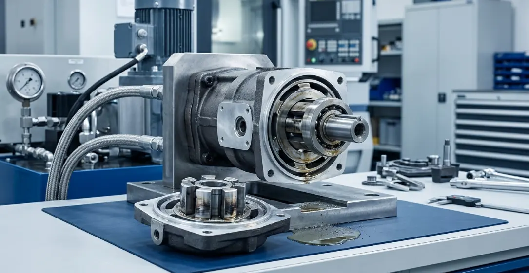
Understanding Vane Pump Operation and Failure Points
How a Vane Pump Works — Basic Mechanics
A vane pump operates by spinning a slotted rotor inside an eccentric cam ring. Vanes slide outward from the rotor slots under centrifugal force and spring pressure, maintaining contact with the cam ring's inner surface to create sealed chambers.
As the rotor turns, these chambers expand at the inlet port (drawing fluid in) and contract at the outlet port (pushing fluid out under pressure). The critical wear surfaces — vane tips, cam ring bore, rotor slots, and port plates — are where most failures originate.
Every component depends on a thin film of hydraulic fluid for lubrication and cooling. When that film is compromised, degradation begins immediately.
Early Warning Signs of Vane Pump Degradation
The earliest indicator of developing problems is typically a change in operating noise. A pump that begins whining, knocking, or producing a higher-pitched sound than normal is communicating internal distress.
Pressure drops under load, increased cycle times, and rising fluid temperatures all signal that internal leakage is increasing. These symptoms mean clearances have opened beyond design tolerances due to hydraulic pump wear.
Flow inconsistencies — jerky actuator movement or slow response — indicate that the pump can no longer maintain consistent displacement. Catching these signs early is the foundation of effective vane pump troubleshooting.
Primary Causes of Vane Pump Failure
Hydraulic Fluid Contamination
Contamination is the single most destructive force acting on vane pump internals. Particulate matter as small as 5 microns — invisible to the naked eye — acts as an abrasive compound between vane tips and the cam ring.
Water ingress accelerates the problem by promoting corrosion, reducing lubricity, and causing hydrogen embrittlement of hardened steel surfaces. Even 0.1% water content can reduce bearing life by 50%.
Chemical breakdown of the fluid itself generates acids and varnish that attack seals and deposit on precision surfaces. Hydraulic system contamination accounts for the majority of premature pump failures across all industrial applications.
Cavitation and Aeration
Pump cavitation causes include starved inlet conditions, restricted suction lines, clogged inlet filters, and fluid that is too viscous for the operating temperature. When fluid cannot fill the expanding pump chambers fast enough, vapor bubbles form in the low-pressure zones.
These bubbles collapse violently when they reach the high-pressure side, generating localized pressures exceeding 100,000 PSI. This micro-jet implosion erodes metal surfaces, creating a characteristic pitted and cratered appearance on vane tips and port plates.
Aeration — air entrained in the fluid from leaking suction fittings, low reservoir levels, or turbulent return lines — produces similar destructive effects. The resulting damage is often misdiagnosed as normal wear rather than a correctable system design issue.
Excessive Operating Temperature
Hydraulic systems operating above 180°F (82°C) experience accelerated degradation across all components. Fluid viscosity drops, thinning the protective lubrication film between vane tips and the cam ring until metal-to-metal contact occurs.
Seal materials harden, crack, and lose their ability to contain pressure. For every 18°F (10°C) above optimal temperature, fluid life is cut in half due to oxidation acceleration.
Thermal expansion of metal components reduces critical clearances, potentially causing vanes to stick in their slots or the rotor to seize against the port plates. Overheating is both a cause and a symptom — internal leakage generates heat, which worsens leakage in a destructive feedback loop.
Improper Fluid Viscosity and Selection
Fluid that is too thin cannot maintain the hydrodynamic film needed to separate moving parts. Fluid that is too thick resists flow into the pump inlet, creating cavitation conditions even with properly sized suction lines.
Each vane pump has a specified viscosity operating range, typically between 13 and 54 centistokes. Operating outside this window — whether from wrong fluid selection or temperature extremes — directly accelerates hydraulic pump wear.
Multi-grade fluids that shear down in service can start within specification but degrade below minimum viscosity within weeks. Regular fluid sampling is the only way to verify that viscosity remains within the acceptable range throughout the service interval.
Misalignment and Shaft Loading
Vane pumps are designed to handle axial and radial loads within tight tolerances. Coupling misalignment — angular, parallel, or axial — introduces side loads that deflect the shaft and create uneven wear patterns.
Shaft deflection causes vanes on one side to press harder against the cam ring while vanes on the opposite side lose contact. This produces asymmetric wear, localized overheating, and premature bearing failure.
Belt-driven or gear-driven installations are particularly susceptible to excessive radial loading. Proper alignment during installation and periodic verification are essential elements of vane pump maintenance that prevent this failure mode.
Running Dry or Insufficient Fluid Level
Even brief periods of dry running cause catastrophic damage to vane pump internals. Without fluid, there is no lubrication film, no cooling, and no hydraulic cushion between moving parts.
Vane tips score the cam ring within seconds, generating metal particles that contaminate the entire system. Temperatures spike instantly, destroying seals and potentially welding vane tips to the cam ring surface.
Low fluid levels that don't completely starve the pump still cause intermittent aeration as the inlet draws air along with fluid. This condition may not produce immediate failure but steadily erodes internal surfaces over days or weeks.
Failure Causes Comparison Table
| Failure Cause | Affected Components | Severity | Typical Time to Failure | Preventability |
|---|---|---|---|---|
| Fluid Contamination | Vanes, cam ring, bearings | High | Weeks to months | High — filtration |
| Cavitation | Vane tips, port plate | Critical | Days to weeks | High — inlet design |
| Overheating | Seals, fluid, all internals | High | Weeks | Moderate — cooling system |
| Wrong Fluid Viscosity | Vanes, cam ring | Moderate | Months | High — fluid selection |
| Misalignment | Shaft, bearings, seals | Moderate | Months | High — installation |
| Dry Running | All internal surfaces | Critical | Minutes to hours | High — level monitoring |
| Normal Wear | Vanes, cam ring | Low | Years | Low — replacement cycle |
Hydraulic System Contamination — A Deeper Look
Sources of Contamination
Built-in contamination originates during manufacturing and assembly. Casting sand, machining chips, weld spatter, and assembly debris remain inside new systems unless properly flushed before commissioning.
Ingressed contamination enters from the external environment through worn shaft seals, degraded breather caps, and cylinder rod retraction. Every time a cylinder rod retracts, it can carry surface contaminants past the wiper seal into the fluid.
Generated contamination is produced internally by normal and abnormal wear. Wear particles from pumps, valves, and actuators circulate through the system, causing secondary damage to other components — a self-accelerating cycle that makes hydraulic system contamination progressively worse without intervention.
Contamination Damage Progression
| Contamination Level (ISO 4406) | Effect on Vane Pump | Recommended Action |
|---|---|---|
| 16/14/11 or cleaner | Normal operation | Routine monitoring |
| 18/16/13 | Accelerated wear begins | Inspect filters, sample fluid |
| 20/18/15 | Significant scoring, efficiency loss | Immediate fluid change and flush |
| 22/20/17+ | Rapid failure imminent | Shutdown and overhaul |
Most vane pump manufacturers specify ISO 18/16/13 or cleaner for acceptable operation. Operating consistently at 20/18/15 can reduce pump life by 75% compared to maintaining 16/14/11 cleanliness levels.
Vane Pump Troubleshooting Guide
Diagnosing Noise-Related Failures
Cavitation whine is a high-pitched, steady screaming sound that increases with pump speed. It indicates inlet starvation and requires immediate attention to suction line restrictions, fluid level, or inlet filter condition.
Mechanical knock is a rhythmic, lower-frequency sound that often correlates with shaft rotation speed. This typically indicates bearing damage, coupling wear, or vanes sticking in their slots.
Bearing rumble is a continuous, rough grinding sound that worsens under load. It signals advanced bearing degradation and imminent failure requiring pump removal for inspection. Effective vane pump troubleshooting starts with training your ear to distinguish these distinct sound signatures.
Pressure and Flow Diagnostic Steps
Begin by measuring system pressure at the pump outlet with a calibrated gauge. Compare readings to the pump's rated output — a drop exceeding 10% under load indicates significant internal leakage.
Install a flow meter to measure actual pump output versus theoretical displacement. Volumetric efficiency below 85% confirms internal wear has opened clearances beyond acceptable limits.
Isolate the pump from the system by deadheading against a gauge (briefly) to determine if pressure loss originates at the pump or downstream. This systematic approach separates pump-related issues from valve or actuator leakage.
Visual Inspection Indicators
Scoring patterns on the cam ring that appear uniformly around the circumference suggest contamination or inadequate lubrication. Localized scoring in one area points to misalignment or a stuck vane.
Vane tip wear profiles reveal operating conditions. Rounded, polished tips indicate normal wear over time. Chipped, pitted tips indicate cavitation. Flat, scored tips indicate abrasive contamination.
Discoloration — blue or straw-colored metal surfaces — confirms overheating. Dark varnish deposits on internal surfaces indicate fluid breakdown from sustained high temperatures. These visual clues during disassembly confirm the root cause identified during vane pump troubleshooting.
Vane Pump Maintenance Best Practices
Preventive Maintenance Schedule
| Interval | Task | Purpose |
|---|---|---|
| Daily | Check fluid level and temperature | Prevent dry running and overheating |
| Weekly | Inspect for leaks and unusual noise | Early detection of developing problems |
| Monthly | Sample hydraulic fluid | Monitor contamination and viscosity |
| Quarterly | Check filter differential pressure | Ensure filtration effectiveness |
| Annually | Full pump inspection and vane measurement | Assess wear and plan replacement |
Adhering to this schedule transforms vane pump maintenance from reactive emergency repairs into predictable, planned service intervals that minimize production disruption.
Fluid Management and Filtration Strategy
Install pressure filters with a beta ratio of β₁₀ ≥ 200 (99.5% efficiency at 10 microns) on the pump outlet to capture wear particles before they circulate through the system. Suction strainers should be 100-mesh minimum to protect the pump inlet without creating restriction.
Kidney-loop (offline) filtration systems continuously polish fluid independent of system operation, maintaining cleanliness levels even during idle periods. This is the most effective strategy for controlling hydraulic system contamination in critical applications.
Establish fluid change intervals based on oil analysis results rather than arbitrary time schedules. Condition-based fluid management reduces waste while ensuring the pump always operates with fluid that meets viscosity and cleanliness specifications.
Installation and Alignment Procedures
Use flexible couplings rated for the application and align pump-to-motor within 0.002 inches (0.05 mm) total indicator reading. Verify alignment under operating temperature, as thermal growth can shift positions after warm-up.
Size suction lines for fluid velocity below 4 feet per second (1.2 m/s) and keep suction line length as short as possible. Every elbow, fitting, and valve in the inlet path adds restriction that contributes to pump cavitation causes.
Design the reservoir with adequate volume (minimum 3x pump flow rate), proper baffling between return and suction ports, and a quality desiccant breather. These installation details prevent the conditions that lead to cavitation, aeration, and contamination ingress from the start.
Frequently Asked Questions (FAQ)
What is the most common cause of vane pump failure?
Hydraulic fluid contamination is the leading cause, responsible for an estimated 70-80% of premature hydraulic pump wear and failure. Particles as small as 5 microns abrade vane tips and cam ring surfaces, progressively increasing internal clearances until the pump can no longer maintain rated pressure and flow. Proper filtration and regular fluid analysis are the most effective preventive measures.
How do I know if my vane pump is cavitating?
A high-pitched whining or screaming noise during operation, accompanied by erratic pressure readings and pitting on vane tips, indicates pump cavitation causes are present. The noise intensifies with increasing pump speed or load. Check for restricted suction lines, clogged inlet strainers, low fluid level, or fluid viscosity that is too high for the operating temperature.
Can a failed vane pump be repaired?
Yes — if the cam ring and rotor are within tolerance, replacing vanes, seals, and bearings during vane pump maintenance can restore performance at a fraction of replacement cost. Most manufacturers publish wear limits for cam ring bore diameter and rotor slot width. However, if the root cause of failure is not corrected, the rebuilt pump will fail again in the same timeframe.
How long should a vane pump last?
With proper vane pump maintenance and clean fluid, industrial vane pumps typically last 15,000–20,000 operating hours. Poor conditions — contaminated fluid, cavitation, overheating, or misalignment — can reduce this to under 2,000 hours. The difference between these extremes is almost entirely determined by system cleanliness and proper operating conditions.
Does running a vane pump at maximum pressure cause failure?
Continuous operation at relief pressure accelerates wear but is not an immediate failure cause. Intermittent pressure spikes and shock loading are more damaging than sustained high pressure because they fatigue metal surfaces and can chip vane tips. Operating consistently at 80-85% of rated pressure optimizes the balance between performance and service life.
How does air in the hydraulic system damage a vane pump?
Aeration causes micro-implosions (cavitation) on internal surfaces, generates excessive heat, and degrades fluid lubricating properties — a key pump cavitation cause in poorly designed systems. Air bubbles compress under pressure, causing spongy and erratic actuator response while simultaneously eroding pump internals. Eliminating air ingress through proper reservoir design, tight suction connections, and adequate fluid levels is essential for pump longevity.



