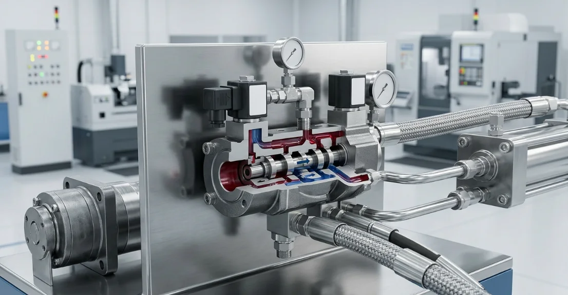
How Does a Hydraulic Directional Control Valve Work?
Learn how hydraulic directional control valves work. Explore spool operation, actuation methods, and real-worl…

Eight nominal sizes, 195–985 cc/rev. Standard 6K, wheel 6KW and bearingless 6KS configurations use different drawings. A separate 6KB parking-brake arrangement is also illustrated.
| Catalogue rating | B6K 195 | B6K 245 | B6K 310 | B6K 390 | B6K 490 | B6K 625 | B6K 800 | B6K 985 |
|---|---|---|---|---|---|---|---|---|
| Nominal displacement (cc/rev) | 195 | 245 | 310 | 390 | 490 | 625 | 800 | 985 |
| Continuous flow (L/min) | 150 | 150 | 150 | 150 | 150 | 150 | 150 | 150 |
| Intermittent flow (L/min) | 170 | 210 | 225 | 225 | 225 | 225 | 225 | 225 |
| Continuous speed (rpm) | 775 | 615 | TBC* | 387 | 307 | 241 | 184 | 153 |
| Intermittent speed (rpm) | 866 | 834 | 485 | 570 | 454 | 355 | 278 | 230 |
| Continuous pressure (bar) | 170 | 170 | 170 | 170 | 170 | 120 | 120 | 120 |
| Intermittent pressure (bar) | 275 | 275 | 275 | 275 | 240 | 140 | 140 | 140 |
| Continuous torque (Nm) | 475 | 615 | 775 | 965 | 1215 | 1125 | 1380 | 1570 |
| Intermittent torque (Nm) | 770 | 980 | 1225 | 1455 | 1685 | 1330 | 1650 | 1875 |
*B6K-310 continuous speed requires confirmation. The summary prints 698 rpm continuous and 485 rpm intermittent, which is inconsistent with the stated duty hierarchy and performance chart. The 698 rpm entry is not offered as a verified operating rating, and no substitute value is assumed.
Other values reproduce the catalogue summary. Individual maximum flow, speed, pressure and torque are not simultaneous operating points. Intermittent duty is limited to 6 seconds per minute. Recommended maximum system temperature: 82°C. Confirm the combined working point and applicable configuration before ordering; brake-version limits are separate.
The Olive Branch Hydraulics B6K hydraulic motor uses disc valve distribution and a geroler mechanism across eight nominal displacements from 195 to 985 cc/rev. The standard motor output shaft uses heavy tapered roller bearing support with a locking arrangement to set bearing clearance.
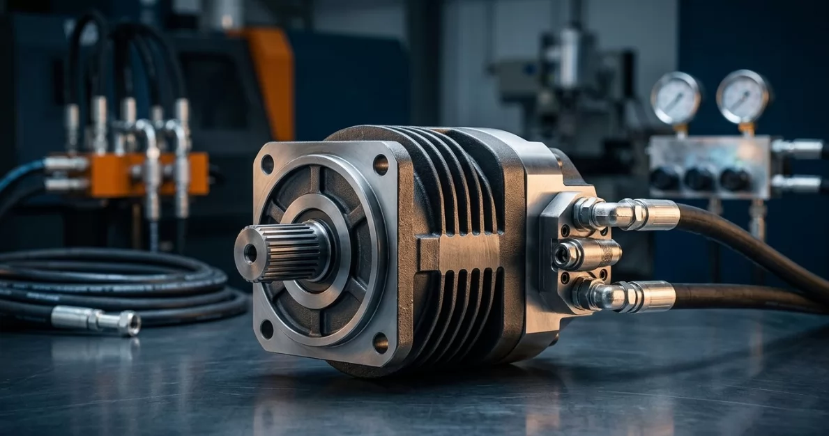
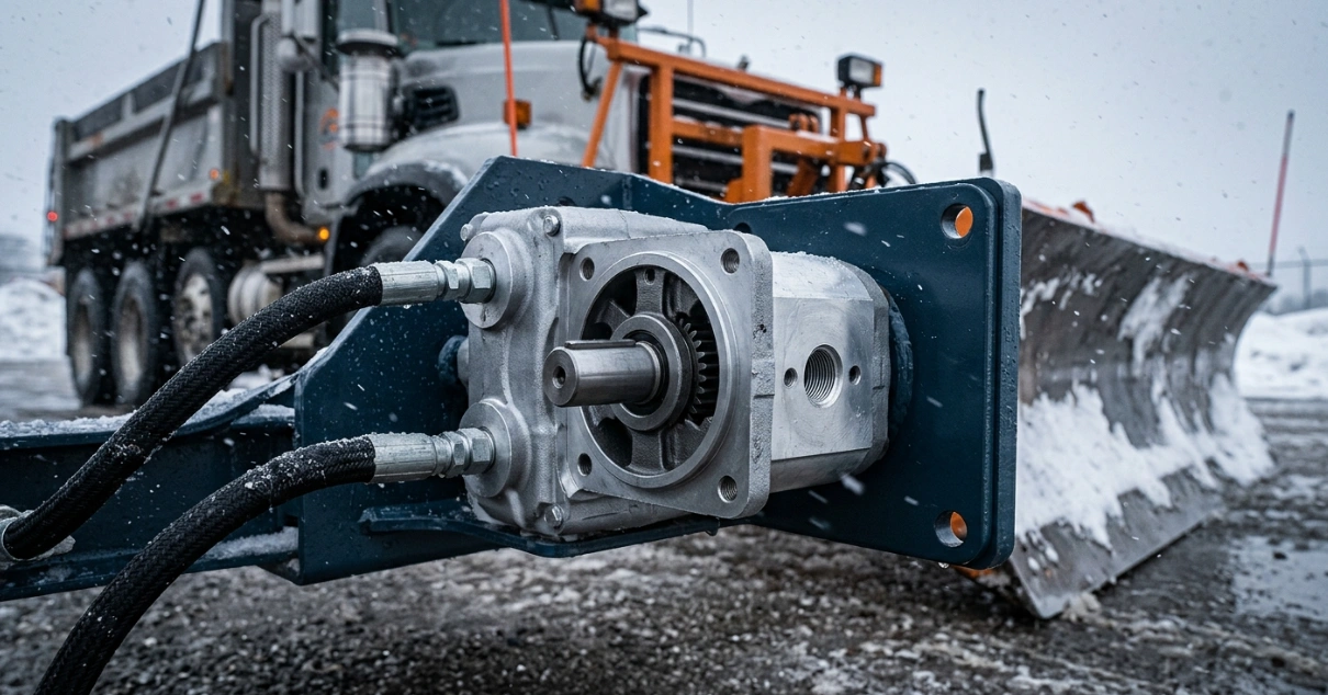
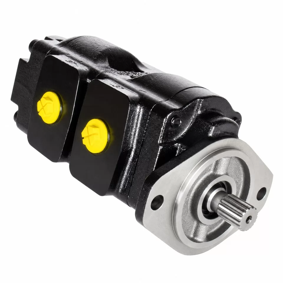
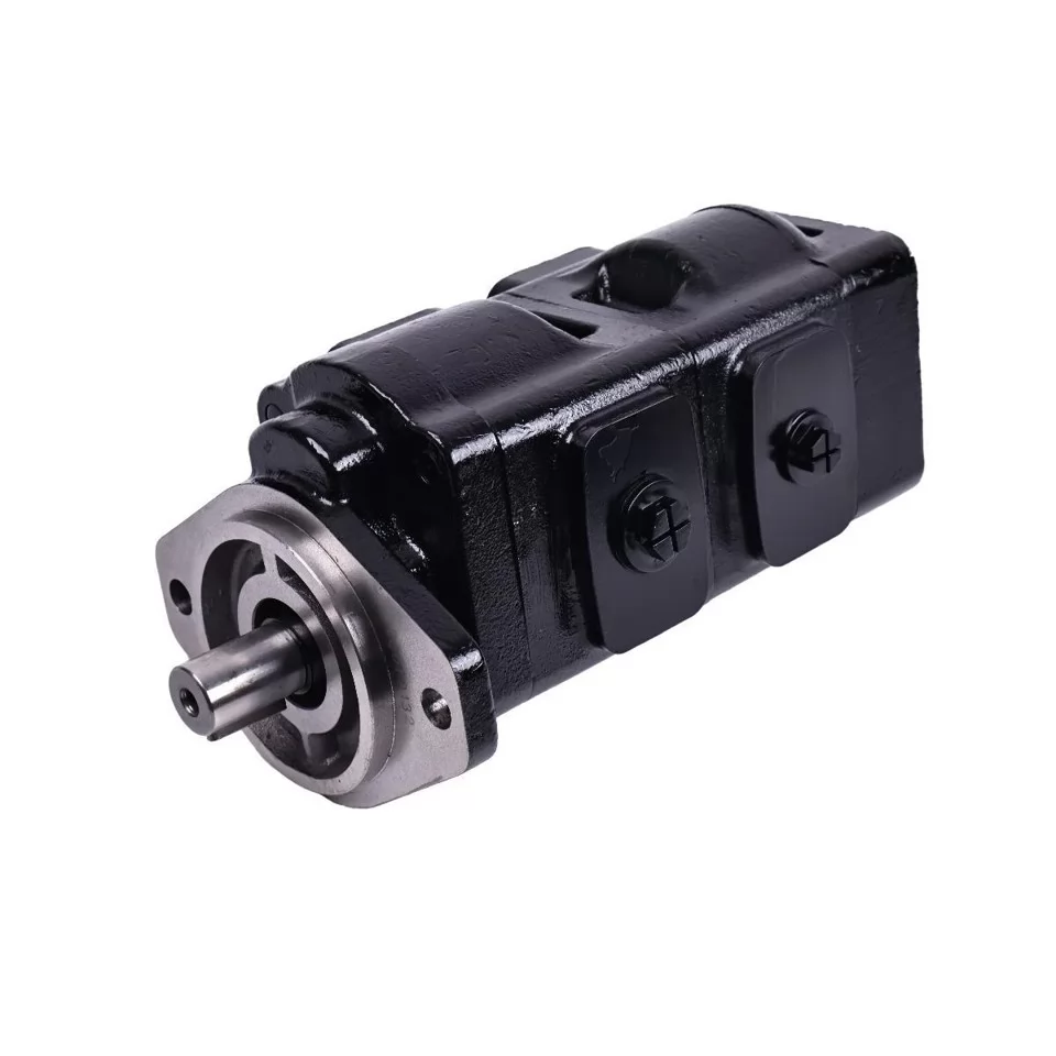
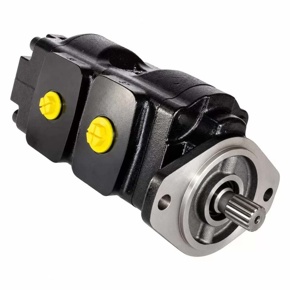
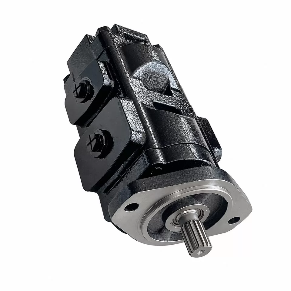
Select the small-flange or large-flange standard motor, 6KW wheel motor, or 6KS bearingless version from its own installation drawing. The three photographs illustrate a standard-family motor from different views; the ordered displacement, shaft, flange and port package must be agreed separately.
| Version | Catalogue options | Selection check |
|---|---|---|
| 6K standard, small flange | F1/F2/F3 flange options; shafts A1–A8 | Pilot, bolt circle, hole diameter, shaft profile and available installation space. |
| 6K standard, large flange | F4 flange; shafts A9–A12 | Separate mounting geometry, shaft projection and motor length. |
| 6KW wheel motor | F5 wheel flange; tapered shafts A13/A14 | Wheel offset, hub interface, radial/axial loads and bearing duty. |
| 6KS bearingless motor | F6 flange; A15 spline output | External shaft support, mating spline, alignment and lubrication path. |
| 6KB parking-brake motor | Separate brake drawing and hydraulic circuit | Brake release, holding load and circuit confirmation; not a standard included brake. |
Small-flange choices differ even when they look similar: the ordering table gives F1 a 125 mm pilot with four 14 mm holes on a 160 mm bolt circle; F2 has a 127 mm pilot with four 14.5 mm holes on a 162 mm circle; F3 uses four 17 mm holes on a 162 mm circle with a 127 mm pilot.
The F4 large-flange drawing specifies a 160 mm pilot, four 18 mm holes and a 200 mm bolt circle. F5 wheel mounting uses a 139.7 mm pilot and 184.15 mm bolt circle with four 14.3 mm holes; F6 bearingless uses a 127 mm pilot and 162 mm bolt circle.
The catalogue contains 24 port packages rather than a universal connection. P1–P9 use the standard staggered or plate-face arrangements; P10–P24 use rectangular arrangements with different main threads, drains and mounting patterns.
| Example | Main ports A/B | Case drain T and mounting check |
|---|---|---|
| P1 | G1, 18 mm thread depth | G1/4; standard staggered face. |
| P2 | M33 × 2, 18 mm depth | M14 × 1.5; standard staggered face. |
| P4 | G3/4, 18 mm depth | G1/4; standard staggered face. |
| P6 | 1-1/16-12 UNF O-ring, as printed, 20 mm depth | 7/16-20 UNF O-ring, minimum 11.5 mm depth; verify thread designation. |
| P7/P8 | Two Ø16 plate-face passages | M14 × 1.5 drain; four M12 mounting threads, different face geometry. |
| P9 | Two Ø19 plate-face passages | 7/16-20 UNF drain; eight 3/8-16 UNC mounting threads. |
| P20/P22/P23 | G3/4, M22 × 1.5 or 7/8-14 UNF, respectively | Four M10 mounting threads; match the specific drain and sealing face. |
Port thread labels containing UN/UNF designations must be verified against the approved thread and sealing specification. Do not infer main-port depth from plate mounting holes, or assume the rectangular and staggered faces share dimensions.
The summary lists 150 L/min continuous flow for all eight sizes. Continuous pressure is 170 bar for the 195 through 490 sizes and 120 bar for the 625, 800 and 985 sizes; continuous torque is displacement-specific and is not a combined maximum-speed operating point.
B6K-310 continuous speed is pending confirmation. Its summary entry of 698 rpm exceeds the listed 485 rpm intermittent speed and conflicts with the chart, so the specification table marks this cell for confirmation rather than presenting it as a verified usable rating.
Other performance-curve boundaries also differ from the summary. Use the summary for initial comparison, then confirm actual torque, rpm, flow and pressure together; intermittent duty must not exceed 6 seconds per minute and recommended system temperature must not exceed 82°C.
Facing the output shaft, the standard diagram gives clockwise rotation with A inlet / B outlet, and counterclockwise rotation with B inlet / A outlet. Confirm the R/L order code and physical port position before connecting the circuit.
The catalogue mentions 310 bar transient inlet and return peaks. These do not establish universal continuous return or seal pressure limits; permissible case pressure, external drain and series/parallel operation depend on the actual seal, speed and hydraulic circuit.
The catalogue identifies agricultural and forestry machinery, oil-industry equipment, machine tools, lifting, construction, drilling and engineering vehicles as application fields. These are selection contexts; no named equipment model fit is established.
| Drive or equipment | Information required |
|---|---|
| Conveyor, feeder or auger | Loaded starting torque, rpm, reduction ratio, reversing/jam duty and chain or belt loads. |
| Forestry or agricultural attachment | Shock loads, stall protection, duty cycle, output coupling and available flow/pressure. |
| Drilling or rotary tooling | Continuous torque, breakaway load, rpm, axial/radial loads and supporting bearing arrangement. |
| Winch or lifting transmission | Load, drum radius, reduction, overspeed control and independently checked load-holding/braking system. |
| Vehicle wheel drive | 6KW configuration, wheel offset, travel speed, radial/axial loads and braking requirements. |
The separate 6KB drawing describes parking-brake service and explicitly excludes dynamic braking. Do not apply the standard motor table as a brake holding-load specification; release pressure, permitted holding torque and working pressure/flow must be confirmed for the selected brake assembly and circuit.
The brake drawing also uses a 395 size label where the standard summary uses 390, so verify the intended configuration from the complete drawing and order code. A hydraulic motor alone should not be treated as an independently verified load-holding system.
Common identification formats include B6K195 / B6K 195 / B6K-195; B6K245 / B6K 245 / B6K-245; B6K310 / B6K 310 / B6K-310; B6K390 / B6K 390 / B6K-390; B6K490 / B6K 490 / B6K-490; B6K625 / B6K 625 / B6K-625; B6K800 / B6K 800 / B6K-800; B6K985 / B6K 985 / B6K-985. The catalogue ordering family uses 6K, 6KW and 6KS; the brake arrangement is separately labelled 6KB/B6KB.
Buyers may compare BM6, BMK6, OMT, BMT or Char-Lynn 6000 families during a replacement search. These comparison names do not establish a direct interchange; the complete shaft, flange, ports, seals, drain, load and ratings must match the application.
Danfoss PowerSource identifies original part 612-1021-1 as a Char-Lynn 6K Series motor with a 195 [11.9] size description. This is an original-number enquiry reference, not a confirmed B6K replacement or an Olive Branch order code.
International terms include motor hidráulico orbital B6K, moteur hydraulique orbital B6K and гидромотор B6K. Include the full original number and dimensions when asking for a match.
B6K uses disc distribution with a geroler mechanism. The standard catalogue motor has heavy tapered roller bearing support; 6KS is a separate bearingless arrangement.
It requires confirmation. The summary prints 698 rpm continuous and 485 rpm intermittent, which conflicts with the duty hierarchy and chart. Do not select an operating speed from that disputed entry.
No. The table lists individual limits, not one combined duty point. Provide required torque, rpm, pump flow, pressure, temperature and duty cycle for a checked selection.
Up to 6 seconds per minute. Use the displacement-specific continuous ratings for sustained duty, subject to the actual configuration and thermal conditions.
No. 6KB is a separate parking-brake arrangement. The catalogue prohibits dynamic braking; release pressure, holding torque, circuit and installation dimensions require separate confirmation.
Viewed facing the output shaft, A inlet and B outlet give clockwise rotation; reversing flow gives counterclockwise rotation. Confirm the ordered R/L code and physical port positions on the drawing.
No. Compare the original full number, displacement, shaft, pilot, bolt pattern, ports, seals, case drain, rotation, ratings and load support. Similar family names or nominal sizes are insufficient.
Send the complete model or original part number, drawing or photographs with measurements, operating point, quantity and destination. Sample availability, MOQ, lead time, packaging and any marking requirements are confirmed for the actual order.
Send Olive Branch Hydraulics the original motor number or configuration drawing, required working point, quantity and destination. Include sample, marking, packaging or documentation requirements so the quotation can state the agreed configuration, terms and lead time.
For a different disc-valve range, compare the B4K orbital hydraulic motor or B2K disc valve motor using each family’s own specifications and drawings.
Learn how hydraulic directional control valves work. Explore spool operation, actuation methods, and real-worl…
BM2 orbital motor review: specs, torque, displacement, and how it stacks up against BM1, BM3, and OEM equivale…
Snowplow motor buying guide for contractors and fleets. Compare hydraulic vs electric, top brands, cold-weathe…
Mixing used motor oil and hydraulic fluid for recycling? Usually fine, but a few costly exceptions can turn pi…
Contact us now for a professional solution and fast quote.
Fill in your info to start a conversation.