

If you've ever watched an excavator at work, you've probably noticed something interesting — the boom lifts while the cab swings around at the same time, smooth as anything. Two separate hydraulic circuits, each doing their own thing, yet somehow perfectly in sync. And all of it runs off one compact unit bolted right to the engine. So what exactly is going on inside a hydraulic double pump that makes this possible? And why do so many machines rely on this setup today?
This technical treatise presents a rigorous examination of the hydraulic double pump, encompassing its fundamental operating principles, classification methodologies, selection parameters, industrial applications, and prescribed maintenance protocols. It is intended to serve as an authoritative reference for hydraulic engineers engaged in the specification of tandem hydraulic pump configurations for capital equipment, as well as for maintenance professionals responsible for the diagnostics and servicing of dual-circuit hydraulic systems.
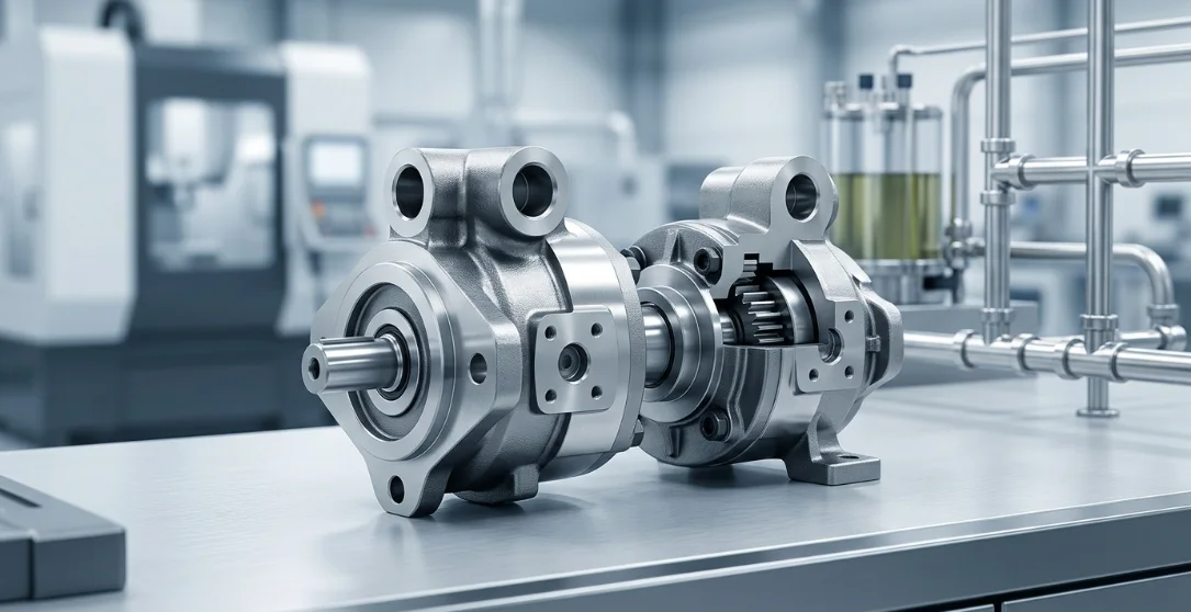
Understanding the Hydraulic Double Pump
Definition and Core Concept
A hydraulic double pump is a single assembly containing two independent pump elements that share one common drive shaft. Each element draws fluid from a reservoir and delivers a separate flow output, effectively providing two hydraulic power sources from one mechanical input.
This design eliminates the need for a second motor or engine power take-off, consolidating hydraulic power generation into a compact, efficient package. The result is a streamlined dual circuit hydraulic system driven by a single prime mover.
How It Differs from a Single Pump
A conventional single pump produces one flow output at one pressure level. If a machine requires two circuits operating at different pressures or flow rates, two separate pumps — each with its own coupling and mounting — are traditionally needed.
A hydraulic double pump solves this by housing two pump sections in one body. Each section maintains independent pressure and hydraulic flow rate control, meaning one circuit can operate at 250 bar while the other runs at 100 bar without interference.
Common Naming Conventions
The industry uses several terms interchangeably for this component. You may encounter "tandem hydraulic pump," "twin pump," "dual pump," or simply "double pump" — all referring to the same fundamental concept of two pump sections sharing a single drive.
Some manufacturers use "tandem" specifically for inline configurations and "twin" for side-by-side arrangements, but these distinctions are not universally standardized. Always verify the actual configuration from the datasheet rather than relying on the trade name alone.
Types of Hydraulic Double Pumps
Double Gear Pump (Hydraulic Gear Pump Configuration)
The double gear pump consists of two hydraulic gear pump sections mounted back-to-back on a shared shaft. Each section uses meshing gears to trap and displace fluid from the inlet to the outlet port.
This configuration is the simplest and most cost-effective option. It offers fixed displacement, robust construction, and high tolerance to contamination — making it ideal for mobile equipment like forklifts and agricultural tractors where reliability outweighs precision.
Double Vane Pump
A double vane pump houses two vane pump cartridges within a single body. Each cartridge features a slotted rotor with sliding vanes that sweep fluid from a large inlet chamber to a smaller outlet chamber.
The balanced loading inherent in vane pump design results in quieter operation and reduced bearing loads. This makes the double vane pump well-suited for industrial applications like injection molding and hydraulic presses where noise control and steady flow matter.
Double Piston Pump
Double piston pumps combine two axial or radial piston groups in one housing. Each group features a swashplate or cam mechanism that converts rotary motion into reciprocating piston action, generating high-pressure fluid output.
These pumps offer variable displacement, the highest pressure capability, and precision flow control. They dominate in demanding applications such as excavators, cranes, and marine systems where both circuits require adaptive performance under varying loads.
Comparison Table
| Feature | Double Gear Pump | Double Vane Pump | Double Piston Pump |
|---|---|---|---|
| Displacement Type | Fixed | Fixed/Variable | Variable |
| Max Pressure (bar) | 250–320 | 180–250 | 350–450 |
| Noise Level | Moderate–High | Low–Moderate | Moderate |
| Cost | Low | Medium | High |
| Typical Use | Mobile equipment | Industrial presses | Excavators, cranes |
Internal Architecture and Working Principle
Shared Drive Shaft Design
The defining feature of every hydraulic double pump is a single input shaft that passes through both pump sections. The prime mover — whether a diesel engine, electric motor, or PTO — turns this shaft, and both sections rotate simultaneously at the same speed.
This shared-shaft approach eliminates the need for a second coupling, bell housing, or motor. It reduces mechanical complexity, minimizes potential misalignment issues, and cuts overall drivetrain length significantly compared to running two independent pumps.
Independent Outlet Ports
Despite sharing a drive shaft, each pump section maintains completely separate hydraulic circuits. Each section has its own suction port drawing from the reservoir and its own discharge port feeding a dedicated circuit.
This architecture creates a fully independent dual circuit hydraulic system. One port may feed the boom cylinders while the other supplies the swing motor — with no internal fluid crossover between sections.
Flow and Pressure Independence
Because each section is hydraulically isolated, a load change on one circuit does not affect the hydraulic flow rate or pressure in the other. If Circuit A stalls against a load and reaches relief pressure, Circuit B continues delivering its rated flow at its own operating pressure.
This independence is critical for machine safety and performance. An operator can rely on consistent steering response even when the implement circuit is under maximum load — a key reason the tandem hydraulic pump dominates mobile machinery design.
Key Performance Specifications
Specifications Table
| Parameter | Typical Range | Unit |
|---|---|---|
| Displacement per section | 4–250 | cc/rev |
| Operating pressure | 150–450 | bar |
| Max speed | 1,500–4,000 | rpm |
| Hydraulic flow rate (combined) | 10–500 | L/min |
| Volumetric efficiency | 92–98 | % |
| Operating temperature | -20 to +80 | °C |
When selecting a hydraulic double pump, always verify that both sections meet the required hydraulic flow rate at the system's actual operating speed — not just the pump's maximum rated speed. Derate performance calculations for elevated temperatures and fluid viscosity variations.
Applications of Hydraulic Double Pumps
Mobile Machinery
Excavators, wheel loaders, and mobile cranes rely heavily on the tandem hydraulic pump to power travel and work circuits independently. One section drives the track motors or wheel motors while the other powers boom, arm, and bucket cylinders.
This separation ensures that travel speed remains consistent regardless of implement load, and vice versa. The compact form factor of a double pump is essential in mobile machines where engine compartment space is at a premium.
Industrial Systems
Hydraulic presses, injection molding machines, and CNC machining centers use a dual circuit hydraulic system for simultaneous operations. One circuit handles clamping force while the other controls feed or injection speed.
In these applications, the double vane pump is often preferred for its low noise output and smooth flow delivery. Factory environments benefit from reduced sound levels, and the consistent flow improves product quality in precision manufacturing.
Agricultural Equipment
Tractors and combine harvesters commonly use a double hydraulic gear pump assembly to run steering and implement circuits from a single engine-driven PTO. The steering section is typically smaller in displacement, ensuring responsive control at all times.
Agricultural environments demand rugged, contamination-tolerant pumps. The simplicity of the gear pump configuration — with fewer internal parts and wider clearance tolerances — makes it the natural choice for field equipment operating in dusty, demanding conditions.
Application Matrix
| Application | Preferred Pump Type | Key Requirement |
|---|---|---|
| Excavators | Double Piston | High pressure, variable flow |
| Forklifts | Double Gear | Compact, cost-effective |
| Plastic Injection | Double Vane | Low noise, steady flow |
| Agricultural tractors | Double Gear | Reliability, simplicity |
| Marine winches | Double Piston | Precise speed control |
Advantages and Limitations
Advantages
- Compact packaging: A hydraulic double pump occupies significantly less space than two separate pumps with individual mountings and couplings.
- Reduced installation cost: Fewer fittings, hoses, mounting brackets, and alignment procedures translate directly to lower build costs and faster assembly.
- Independent dual circuit hydraulic system control: Each section operates autonomously, allowing different pressures and flow rates without cross-circuit interference.
- Lower power loss: A shared drive shaft eliminates one coupling and bearing set, reducing parasitic friction losses compared to running two standalone pumps.
- Simplified maintenance: One drain line, one mounting point, and one shaft seal to monitor rather than duplicating these across two separate units.
Limitations
- Full unit replacement risk: If one section fails catastrophically, the entire tandem hydraulic pump may need to be removed for repair or replacement, increasing downtime.
- Slightly higher weight: The combined housing is heavier than a single pump, though still lighter than two independent pumps with separate mountings.
- Manufacturing precision: Shaft alignment between sections must be held to tight tolerances during production, adding manufacturing complexity.
- Limited modularity: Changing the displacement of one section typically requires replacing the entire pump rather than swapping a single component.
Selection Criteria for a Hydraulic Double Pump
Matching Flow and Pressure Requirements
Size each pump section independently based on the actuator demand it serves. Calculate the required hydraulic flow rate using the formula: Flow (L/min) = Actuator speed (m/min) × Actuator area (cm²) ÷ 10.
Add a 5–10% margin for system losses including valve pressure drops, hose friction, and internal leakage. Ensure the selected pump's maximum continuous pressure rating exceeds your circuit's relief valve setting by at least 10% to avoid operating at the pump's absolute limit.
Displacement Ratio Considerations
Many applications require unequal flow to each circuit. A hydraulic double pump can be specified with different displacements per section — for example, 40 cc/rev for the work circuit and 20 cc/rev for the steering circuit.
Manufacturers offer standard displacement combinations, but custom ratios are available for OEM orders. When selecting ratios, consider that both sections turn at the same speed, so flow differences can only be achieved through displacement differences, not speed variation.
Mounting and Drive Compatibility
Verify that the pump's mounting flange conforms to the appropriate SAE standard (SAE A, B, C, or D) for your power source. Check shaft spline or keyed shaft compatibility with the engine PTO, gearbox, or electric motor coupling.
Consider the pump's rotation direction (clockwise or counterclockwise viewed from the shaft end) and ensure it matches your drive arrangement. Incorrect rotation will cause immediate cavitation damage and pump failure.
Maintenance Best Practices
Fluid Cleanliness and Filtration
Fluid contamination is the leading cause of hydraulic pump failure. For a double gear pump, maintain fluid cleanliness to ISO 4406 code 19/17/14 or better. Double vane pumps and piston pumps require cleaner fluid — target ISO 17/15/12 or better.
Install return-line filtration with a beta ratio of β₁₀ ≥ 75 as a minimum. For piston-type tandem hydraulic pumps, add a pressure-line filter rated at 10 microns absolute to protect downstream valves and actuators.
Seal and Wear Inspection Schedule
Monitor internal leakage by measuring case drain flow from the pump housing. A gradual increase in case drain flow indicates wear in bearings, gears, or piston bores. Establish a baseline at commissioning and track trends quarterly.
Replace shaft seals at the manufacturer's recommended interval — typically every 5,000–8,000 operating hours — or immediately if external leakage appears. Inspect mounting bolts for looseness every 500 hours, as vibration can gradually back out fasteners.
Common Failure Modes
Cavitation: Caused by restricted suction lines, clogged inlet filters, or fluid viscosity too high at cold start. Listen for a distinctive rattling or knocking sound. Correct by verifying inlet vacuum stays below 0.3 bar absolute.
Contamination damage: Abrasive particles score gear faces, vane tips, or piston bores, increasing internal leakage and reducing volumetric efficiency. Prevention through proper filtration is far more cost-effective than repair.
Shaft seal leakage: Excessive case pressure, misalignment, or aged seal material causes external oil leaks at the shaft. Verify that the case drain line is unrestricted and that back-pressure does not exceed the manufacturer's limit — typically 1–2 bar.
Frequently Asked Questions (FAQ)
What is the main advantage of a hydraulic double pump over two separate pumps?
A hydraulic double pump saves space, reduces plumbing complexity, and lowers overall system cost by driving two independent circuits from a single shaft and housing. It eliminates the need for a second motor coupling, mounting bracket, and alignment procedure — simplifying both installation and maintenance.
Can each section of a tandem hydraulic pump operate at different pressures?
Yes. Each section has independent outlet ports and is protected by its own relief valve. This allows one circuit to operate at 300 bar while the other runs at 150 bar without any interaction or pressure bleed-through between sections.
Is a double vane pump quieter than a double gear pump?
Generally yes. The balanced design of a double vane pump produces lower pressure pulsations and significantly reduced noise — typically 5–10 dB(A) quieter than an equivalent hydraulic gear pump configuration. This makes vane pumps preferred for indoor industrial environments where operator comfort matters.
How do I determine the correct hydraulic flow rate for each pump section?
Calculate the required flow using: actuator speed × actuator displacement for each circuit. Then add a margin of 5–10% to account for system losses including valve drops, hose friction, and internal pump leakage. Always verify calculations against the actual duty cycle to avoid undersizing.
Can a hydraulic double pump be used in a dual circuit hydraulic system with different fluids?
Standard double pumps share a common case drain, meaning both sections operate in the same fluid. This makes running different fluids impractical in most configurations. Separate-case designs do exist for specialized applications, but they are uncommon and significantly more expensive.
What causes uneven wear between the two sections?
Imbalanced loading is the primary cause — for example, operating one section continuously at relief pressure while the other runs unloaded. Contamination entering one circuit preferentially, mismatched filtration between circuits, or thermal imbalance can also accelerate wear in one section relative to the other.



