

Hydraulic power units are engineered to deliver operating pressures of up to 10,000 PSI, serving as the principal motive force in applications ranging from heavy construction excavators to aerospace actuation systems such as aircraft landing gear. Despite their ubiquity across critical industrial sectors, these systems remain largely unfamiliar to the general public. This raises a fundamental question: what are the defining characteristics that establish the hydraulic power pack as an indispensable component of modern industrial machinery?
If you work with heavy equipment, design automation systems, or keep industrial machinery running, you've probably dealt with hydraulic power packs more than once. Here's a practical look at how they work, what's inside them, and how to pick the right one for the job.
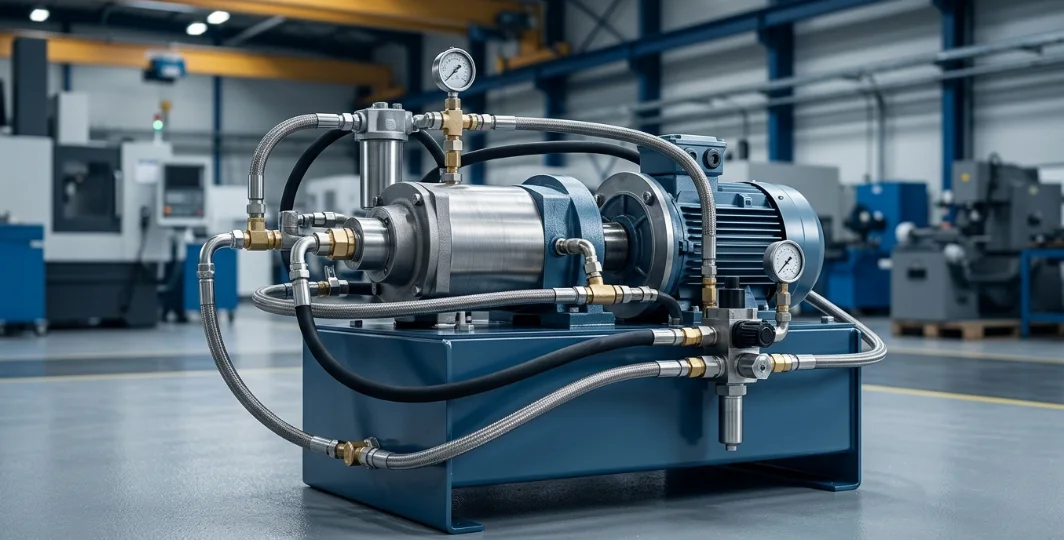
Understanding the Hydraulic Power Pack
Definition and Core Function
A hydraulic power pack is a self-contained unit that generates, controls, and delivers hydraulic fluid under pressure to drive actuators and machinery. It serves as the central energy source in any hydraulic system, converting electrical or mechanical energy into controlled fluid power.
Think of it as the heart of a hydraulic circuit. Without the hydraulic power unit pumping pressurized fluid through the system, cylinders won't extend, motors won't turn, and work simply doesn't get done.
How a Hydraulic Power Pack Works
The operating cycle of a hydraulic power pack follows a precise sequence that repeats continuously during operation. Understanding each step helps you diagnose problems and optimize performance.
- Motor activation: An electric or diesel motor (the hydraulic motor assembly) starts and converts electrical or fuel energy into mechanical rotation.
- Pump engagement: The rotating shaft drives the hydraulic pump system, which creates a vacuum that draws fluid from the hydraulic fluid reservoir.
- Pressurization: The pump converts low-pressure fluid into high-pressure flow, typically between 1,000 and 10,000 PSI depending on the application.
- Valve control: The pressurized fluid passes through the hydraulic pressure valve assembly, which directs flow to the correct actuator at the proper pressure.
- Work output: Fluid enters the actuator (cylinder or motor), converting hydraulic energy back into mechanical force or motion.
- Return cycle: Spent fluid returns to the hydraulic fluid reservoir through return-line filters, where it cools and is conditioned for reuse.
Key Components Table
Every hydraulic power pack contains six core components working together. The table below outlines each part, its function, and the common types you'll encounter in the field.
| Component | Function | Common Types |
|---|---|---|
| Hydraulic Motor Assembly | Converts electrical or fuel energy to mechanical rotation | AC electric, DC electric, diesel |
| Hydraulic Pump | Converts mechanical energy to fluid flow | Gear, vane, piston |
| Hydraulic Fluid Reservoir | Stores and conditions fluid | Vented, pressurized |
| Hydraulic Pressure Valve | Controls pressure and flow direction | Relief, directional, check |
| Filters | Removes contaminants from fluid | Suction, return line, pressure |
| Heat Exchanger | Maintains optimal fluid temperature | Air-cooled, water-cooled |
Types of Hydraulic Power Packs
Classification by Power Source
The power source determines where and how a hydraulic power unit can be deployed. Choosing the wrong type for your environment leads to inefficiency, safety hazards, or outright failure.
| Type | Power Source | Best Application |
|---|---|---|
| Electric | AC/DC motor | Indoor use, factory automation |
| Diesel/Gas | Combustion engine | Remote or outdoor job sites |
| Pneumatic | Air-driven motor | Hazardous or explosive environments |
| Manual/Hand | Human-operated lever | Emergency backup, light-duty tasks |
Electric hydraulic power packs dominate indoor industrial settings because they run cleanly, quietly, and efficiently. Diesel units excel on construction sites and remote locations where grid power isn't available.
Pneumatic power packs eliminate ignition sources entirely, making them the standard choice in chemical plants, paint booths, and mining operations with explosive atmospheres.
Classification by Size and Capacity
Micro hydraulic power packs deliver flow rates under 1 GPM at pressures up to 3,000 PSI. They feature reservoirs under 1 gallon and power small clamping devices, medical equipment, and compact automation tools.
Mini hydraulic power packs operate between 1–5 GPM with pressures reaching 5,000 PSI. Reservoir capacities range from 1–10 gallons, making them suitable for machine tools, lift tables, and mobile equipment.
Standard hydraulic power units produce 5–30 GPM at pressures up to 5,000 PSI. With 10–100 gallon reservoirs, they handle most manufacturing, construction, and material handling applications.
Industrial-grade hydraulic power units exceed 30 GPM with pressures reaching 10,000 PSI. These large-scale systems feature reservoirs of 100+ gallons and drive heavy presses, offshore equipment, and large-scale manufacturing lines.
Applications Across Industries
Construction and Heavy Equipment
Excavators, bulldozers, cranes, and concrete pumps all rely on hydraulic power packs to deliver the immense force needed for earthmoving and material handling. A single excavator may require a hydraulic pump system producing 5,000+ PSI to operate its boom, arm, and bucket simultaneously.
Mobile hydraulic power units on construction sites typically use diesel-driven motors for independence from electrical infrastructure. These systems must withstand extreme vibration, dust, and temperature swings while maintaining reliable output.
Manufacturing and Factory Automation
Press brakes, injection molding machines, CNC equipment, and robotic assembly lines depend on precise hydraulic control. Factory-based hydraulic power packs use electric motors for clean, efficient operation with exact pressure regulation.
In automated manufacturing, the hydraulic power unit must deliver repeatable force and speed across thousands of cycles per day. Consistency in the hydraulic pressure valve settings directly impacts product quality and reject rates.
Aerospace and Marine Systems
Aircraft landing gear, flight control surfaces, and cargo doors operate through aerospace-grade hydraulic power packs designed for extreme reliability. These systems use specialized fire-resistant fluids and redundant pump configurations to ensure fail-safe operation.
Marine applications include steering gear, winches, hatch covers, and stabilizer systems on vessels. Saltwater environments demand corrosion-resistant components and sealed hydraulic fluid reservoirs that prevent moisture contamination.
Agriculture and Forestry
Tractors, harvesters, log splitters, and forestry processors use hydraulic power packs to handle heavy loads in rugged outdoor conditions. Agricultural hydraulic systems must tolerate wide temperature ranges, from freezing mornings to hot afternoon operation.
Modern precision agriculture equipment uses electronically controlled hydraulic power units for variable-rate application, auto-steering, and implement depth control. The hydraulic motor assembly in these systems often runs continuously for 12+ hours during peak season.
Selecting the Right Hydraulic Power Unit
Critical Specifications Table
Matching the hydraulic power pack to your application requires evaluating five key specifications. Getting any one wrong can result in premature failure, poor performance, or wasted energy.
| Specification | What to Evaluate | Why It Matters |
|---|---|---|
| Operating Pressure (PSI/Bar) | System force requirements | Undersizing causes component failure |
| Flow Rate (GPM/LPM) | Actuator speed needs | Directly affects cycle time |
| Reservoir Capacity | Duty cycle and cooling needs | Prevents overheating and fluid degradation |
| Motor Power (HP/kW) | Pump demand calculation | Impacts efficiency and energy cost |
| Mounting Configuration | Available space and orientation | Determines installation feasibility |
Sizing formula: Motor HP = (GPM × PSI) ÷ 1,714 × efficiency factor. Always add a 20% safety margin to account for system losses and peak demand spikes.
Environmental and Duty Cycle Considerations
Temperature range: Standard hydraulic fluid operates effectively between -20°F and 200°F. Extreme cold requires low-viscosity fluids, while high-heat environments need synthetic oils and oversized cooling systems.
Contamination exposure: Dusty, wet, or corrosive environments demand sealed reservoirs, enhanced filtration, and protective enclosures. Contamination is the leading cause of hydraulic system failure, responsible for up to 80% of breakdowns.
Continuous vs. intermittent operation: Continuous-duty hydraulic power packs require larger reservoirs (typically 3× pump flow rate per minute) and dedicated heat exchangers. Intermittent-duty units can use smaller reservoirs because natural cooling occurs during off-cycles.
Maintenance and Troubleshooting
Preventive Maintenance Schedule
Consistent preventive maintenance extends the life of a hydraulic power pack from a few thousand hours to 20,000+ hours. Follow this schedule as a baseline, adjusting intervals based on your operating environment and duty cycle.
- Daily: Check fluid level in the hydraulic fluid reservoir, inspect for visible leaks, monitor operating temperature
- Weekly: Examine hoses and fittings for wear, check pressure gauge readings against baseline
- Every 500 hours: Replace return-line filters, sample fluid for contamination analysis
- Every 1,000 hours: Replace pressure filters, inspect pump and motor seals, check hydraulic pressure valve settings
- Every 2,000 hours: Full fluid change (or as indicated by oil analysis), inspect reservoir interior, clean heat exchanger
- Annually: Complete system audit including valve calibration, accumulator pre-charge check, and electrical connection inspection
Common Failures and Solutions
When a hydraulic power pack malfunctions, quick diagnosis saves downtime and prevents secondary damage. The table below covers the most frequent symptoms and their corrective actions.
| Symptom | Likely Cause | Corrective Action |
|---|---|---|
| Overheating | Low fluid level, blocked cooler | Top up fluid, clean heat exchanger |
| Slow operation | Worn pump, internal leaks | Replace pump, check and replace seals |
| Excessive noise | Cavitation, air in system | Check suction line for leaks, bleed air |
| Pressure drop | Faulty hydraulic pressure valve | Inspect and replace valve |
| Foaming fluid | Water contamination, wrong fluid | Drain and replace fluid, find water source |
| Erratic actuator movement | Air in lines, sticking valve | Bleed system, clean or replace valve |
Frequently Asked Questions (FAQ)
What is the difference between a hydraulic power pack and a hydraulic power unit?
They are the same device. The terms "power pack" and "hydraulic power unit" are used interchangeably throughout the industry. Both refer to the self-contained assembly of motor, pump, reservoir, valves, and controls that supplies pressurized fluid to a hydraulic system.
How long does a hydraulic power pack last?
With proper maintenance, a well-built hydraulic power pack typically lasts 10,000 to 20,000 operating hours. Lifespan depends heavily on duty cycle, operating environment, fluid cleanliness, and adherence to maintenance schedules. Industrial units in clean factory environments often exceed 20,000 hours.
What fluid does a hydraulic power pack use?
Most hydraulic power packs use petroleum-based hydraulic oil in ISO viscosity grades 32, 46, or 68. The correct grade depends on operating temperature and system requirements. Biodegradable fluids (vegetable-based) are used in environmentally sensitive areas, while fire-resistant fluids (water-glycol or phosphate ester) serve foundries and steel mills.
Can a hydraulic power pack run continuously?
It depends on the design. Continuous-duty hydraulic power units feature larger hydraulic fluid reservoirs, dedicated cooling systems, and components rated for sustained operation. Intermittent-duty units require cool-down periods between cycles and will overheat if run continuously. Always verify the duty cycle rating before specifying a unit for continuous applications.
How do I size a hydraulic power pack for my application?
Start by calculating the required pressure (based on force needs) and flow rate (based on actuator speed). Multiply these to determine the motor horsepower using the formula: HP = (GPM × PSI) ÷ 1,714. Then match the reservoir size to your duty cycle — a general rule is 3× the pump's GPM rating for continuous duty. Finally, factor in thermal dissipation needs and add a 20% safety margin.
What maintenance does a hydraulic pump system require?
A hydraulic pump system requires regular fluid analysis (every 500 hours), filter changes every 500–1,000 hours, seal inspections at 1,000-hour intervals, and annual valve calibration checks. Daily visual inspections for leaks and fluid level monitoring are also essential. Keeping fluid clean and at the correct level prevents the majority of pump failures.



