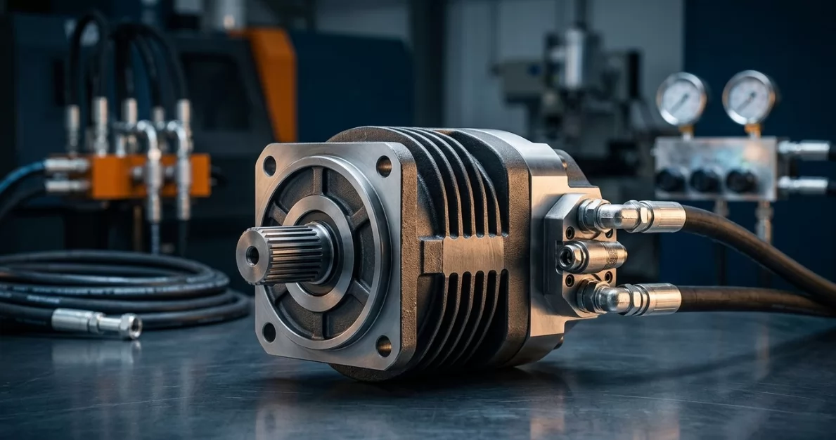
How Does a Hydraulic Directional Control Valve Work?
Learn how hydraulic directional control valves work. Explore spool operation, actuation methods, and real-worl…

BMSY disc valve orbital motor from manufacturer Olive Branch Hydraulics, EXW Hebei, China. Ten nominal sizes appear in the P107 performance summary. The figures below are reference transcriptions; conflicting curve and mounting data require written configuration and combined-duty confirmation before selection.
| Nominal size cc/rev | Flow C/I L/min | Speed C/I rpm | Pressure C/I bar | Torque C/I Nm |
|---|---|---|---|---|
| BMSY80 | 75 / 75 | 799 / 908 | 170 / 275 | 195 / 305 |
| BMSY100 | 75 / 95 | 742 / 924 | 170 / 275 | 245 / 395 |
| BMSY125 | 75 / 95 | 576 / 720 | 170 / 275 | 315 / 550 |
| BMSY160 | 75 / 115 | 477 / 713 | 170 / 275 | 380 / 530 |
| BMSY195 | 75 / 115 | 385 / 577 | 170 / 240 | 455 / 625 |
| BMSY245 | 75 / 115 | 308 / 462 | 170 / 240 | 555 / 765 |
| BMSY305 | 75 / 115 | 246 / 365 | 140 / 205 | 560 / 805 |
| BMSY395 | 75 / 115 | 191 / 265 | 140 / 170 | 700 / 890 |
| BMSY490 | 75 / 115 | 153 / 230 | 130 / 150 | 838 / 956 |
| BMSY630 | 75 / 115 | 112 / 168 | 130 / 150 | 1063 / 1228 |
C = continuous; I = intermittent, at most 6 seconds per minute. Recommended maximum system temperature 82°C. Do not combine maximum pressure and maximum speed. Standard, wheel and bearingless versions need individual interface review; no brake rating is published. Nominal codes are not verified actual swept volumes. BMSY630 dimensions are not provided in the included mounting/order tables.
The BMSY hydraulic motor is a disc valve orbital motor in ten nominal displacements, BMSY80 through BMSY630, with catalogue continuous torque of 195–1063 Nm. Standard flange, wheel mount and bearingless hydraulic motor builds are manufactured and supplied EXW Hebei, China.
Every quotation is matched to a confirmed drawing and order code. The catalogue summary table is for first comparison only, and final selection follows our written confirmation of your combined duty point.
Five-piece body. Disc valve distribution. Roller stator–rotor set.
The bearingless version shortens the drive package. The trade-off is that the gearbox or hub must take all radial and axial loads.
Selection comes down to four checks: continuous torque, continuous pressure, speed at your available flow and duty cycle. Intermittent values apply for no more than 6 seconds in any minute, and maximum speed and maximum pressure are never rated as a simultaneous combination.
Model search spellings: BMSY80 / BMSY 80 / BMSY-80; BMSY100 / BMSY 100 / BMSY-100; BMSY125 / BMSY 125 / BMSY-125; BMSY160 / BMSY 160 / BMSY-160; BMSY195 / BMSY 195 / BMSY-195; BMSY245 / BMSY 245 / BMSY-245; BMSY305 / BMSY 305 / BMSY-305; BMSY395 / BMSY 395 / BMSY-395; BMSY490 / BMSY 490 / BMSY-490; BMSY630 / BMSY 630 / BMSY-630. These are nominal size aliases, not complete order codes. BMSY315 and BMSY475 are printed drawing references requiring separate confirmation, not verified aliases for 305/490. No OEM material-number cross-reference is verified on this page.
Equivalent search terms are motor hidráulico orbital BMSY and motor orbital con válvula de disco (ES), moteur hydraulique orbital BMSY and moteur orbital à distributeur à disque (FR), and гидромотор BMSY and орбитальный гидромотор с торцевым распределением (RU).
Augers, conveyors and wheel drives place different loads on the same displacement. The table below is a first filter by catalogue torque. Exact machine compatibility requires a full configuration review.
| Equipment | Typical BMSY Build | Catalogue Starting Point | Confirm Before Ordering |
|---|---|---|---|
| Conveyors | Standard mount | Size by continuous torque at line speed | Start/stop frequency, duty cycle, drain routing |
| Augers | Standard mount | 395–630 cc list 700–1063 Nm continuous | Stall and shock events against the 6 s/min intermittent limit |
| Rotary attachments | Standard mount | 125–245 cc list 315–555 Nm continuous | Reversing frequency, back-pressure, case pressure |
| Engineered wheel drives | Wheel mount | Size by wheel torque and travel speed | Radial load, hub interface, 315/475 drawing labels |
| Bearingless gearbox drives | Bearingless | Sizes per p. 115 bearingless table | External bearing, A17 spline mating and any separately engineered load-holding system |
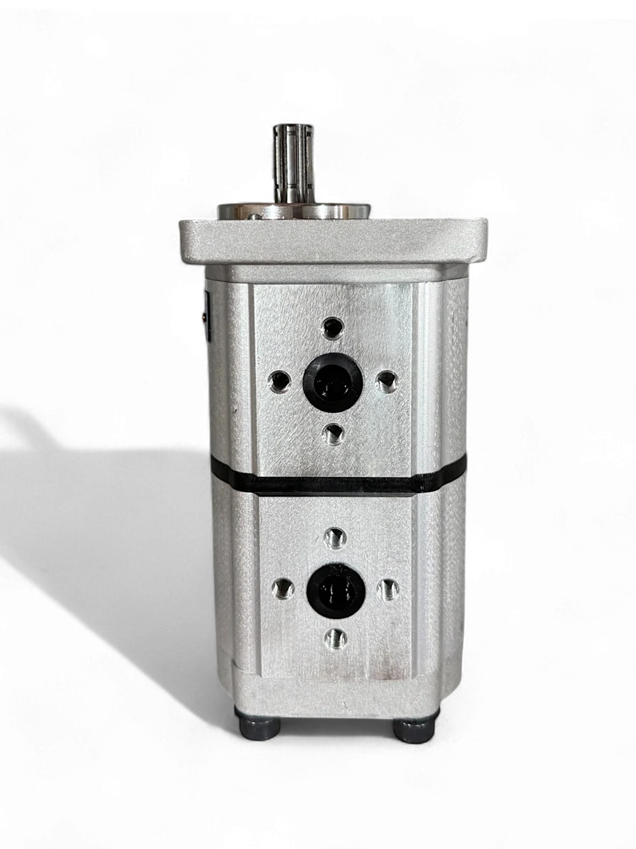
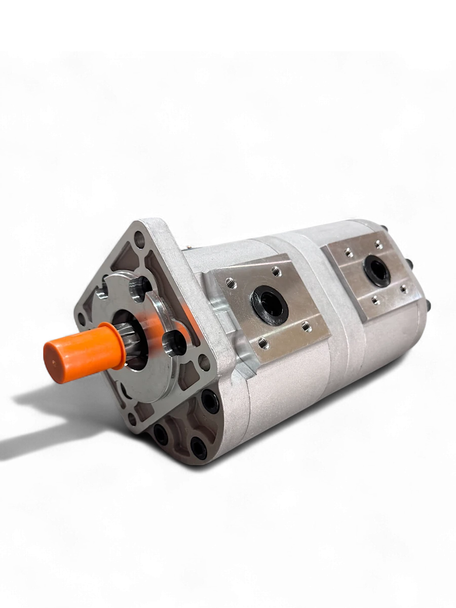
The gallery contains the complete P107–P116 source pages. Photos illustrate a standard keyed-shaft family configuration, not every size, wheel mount or bearingless version. Use the selected shaft, flange, port and drain codes together with an approved drawing.
F1 is the two-hole elongated flange, F2 the four-hole square flange, F3 the four-hole elongated flange, and F4 the 120 mm square flange with a 100 mm pilot and four 13 mm holes. F5 is the six-hole elongated flange. F1/F2/F3/F5/F6 use an 82.5 mm nominal pilot in the order table, but pilot projection and hole geometry differ. F6 is a smaller square flange with four 11.5 mm through-holes on a 106.4 mm bolt circle in the drawing. F2 is labelled 105×105 in the order table while its drawing shows 106.4 mm centres: confirm the final hole pattern rather than treating these figures as identical.
F7 is the wheel flange: nominal 125 mm pilot, four 13.5 mm holes on a 160 mm bolt circle. F8 is a two-hole elongated flange with 11 mm holes at 109 mm centres. F9 is the larger two-hole flange with a 101.6 mm pilot, 14.3 mm holes and 146.05 mm centres. F10 is the round bearingless flange, 100 mm pilot, four 11 mm holes on a 125 mm bolt circle. F11 is the square bearingless flange, 101.6 mm pilot, four 13.5 mm holes on a 127 mm bolt circle. The complete drawings govern tolerances and orientation.
The P110 standard and wheel tables label sizes 315 and 475, whereas the P107 performance table uses 305 and 490. The P115 bearingless tables and P116 order table use 305 and 490. These labels are not confirmed equivalents. No 630 mounting dimensions or 630 order-table entry is supplied here; request an approved 630 drawing.
| P110 printed size | H | Standard L | Wheel L (mm) |
|---|---|---|---|
| 80 | 14.4 | 166 | 136 |
| 100 | 17.8 | 169 | 139 |
| 125 | 22.5 | 174 | 144 |
| 160 | 28.9 | 181 | 150 |
| 195 | 35.6 | 187 | 158 |
| 245 | 44.6 | 196 | 167 |
| 315 | 44.6 | 196 | 167 |
| 395 | 56 | 180 | 192 |
| 475 | 68 | 192 | 204 |
H and L are the labels on the source drawings, not universally interchangeable overall-length definitions. The standard 395/475 L values are shorter than some smaller-size entries, so the table must not be used to infer an unconfirmed envelope. P115 bearingless printed sizes 80/100/125/160/195/245/305/395/490 have L 122/124/129/136/142/151/151/163/179 mm respectively. Confirm the full assembly and shaft projection separately.
Keyed examples include A1 Ø25 mm, A2 Ø32 mm with a 10×8×45 key, A3 Ø25.4 mm with a 6.35×6.35×32 key, A5 Ø31.75 mm with a 7.96×7.96×31.75 key and A9 Ø30 mm with a 10×8×45 key. A1 is drawn with an 8×7×32 key on P112, while the order table prints 8×7×28; confirm the engagement length. A6 and A8 are 14-tooth 12/24 DP, 30° involute splines with different end threads; A15 is a different 13-tooth 16/32 DP spline. Rectangular spline drawings A4/A10/A11/A14/A16 differ in tooth dimensions or projection; a shared tooth count does not establish a fit.
A12 uses a nominal Ø35 mm taper 1:10, key 6×6×20 and M20×1.5 end thread. A13 instead uses a Ø31.75 mm taper 1:8, 7.96 mm square key and M24×1.5 end thread. The P113 200±10 Nm tightening value belongs only to the illustrated A13 shaft nut, not flange bolts or all shaft types. Bearingless A17 is a 12-tooth 12/24 DP, 30° spline; it is not the 14-tooth standard shaft. The host gearbox or hub must carry the shaft loads and provide the required lubrication arrangement.
P1/P6/P10 use G1/2 main ports; P2/P5/P11 use M22×1.5; P3/P7/P12 use 7/8-14 UNF O-ring ports; P4 uses 1/2 NPT. P1–P4 show a two-M10 face connection pattern, P5–P7 a different three-M10 pattern, and P8/P9 two Ø13 open ports with a three-M10 pattern. P13/P14/P15 show four-port arrangements using G1/2, M22×1.5 or 7/8-14 UNF respectively. P16 is a special rear/side port arrangement with separate front drain: confirm the actual main-thread description and port allocation against the drawing, since the order-table wording differs.
Case-drain options include G1/4, M14×1.5 and 7/16-20 UNF depending on the port code. A mounting-bolt thread is not the main fluid-port thread. Agree the seal form, thread depth, return pressure and external drain before installation.
Related products: compare the independently specified BMV disc valve motor and BMT orbital motor. Similar names or nominal displacement do not establish interchangeability.
MOQ, lead time and sample terms are quoted for each configuration. Small trial orders are accepted.
No. It is an initial comparison only, because the pp. 108–109 curves differ from it, so we confirm your combined duty point in writing before selection.
No. The catalogue does not rate that combination, and intermittent values are limited to 6 seconds per minute.
No equivalence is confirmed. The 315 and 475 labels on the p. 110 drawing must be checked against the 305 and 490 performance sizes before any selection.
Only from a confirmed drawing. The 630 size is not shown on the catalogue mount drawing or order table, and we do not estimate its dimensions.
Not automatically. Send the original nameplate and drawing so we can compare the full code, mounting, shaft, sealing, ports, drain, rotation, circuit, loads and rated duty before approving any replacement.
It requires an external bearing in the gearbox or hub, and the shaft uses spline A17 (12 teeth, 12/24 DP, 30°). No brake rating is published for this build.
Clockwise viewed facing the shaft with A as inlet and B as outlet. Reverse the flow for counter-clockwise rotation.
No. BMVS belongs to the BMV series and is quoted separately.
We supply order-specific documents verified for your shipment. Factory inspection in Hebei is available on request.
Send these six items and we return a factory-direct EXW Hebei quotation with written duty confirmation, sample terms and lead time for your configuration.
Learn how hydraulic directional control valves work. Explore spool operation, actuation methods, and real-worl…
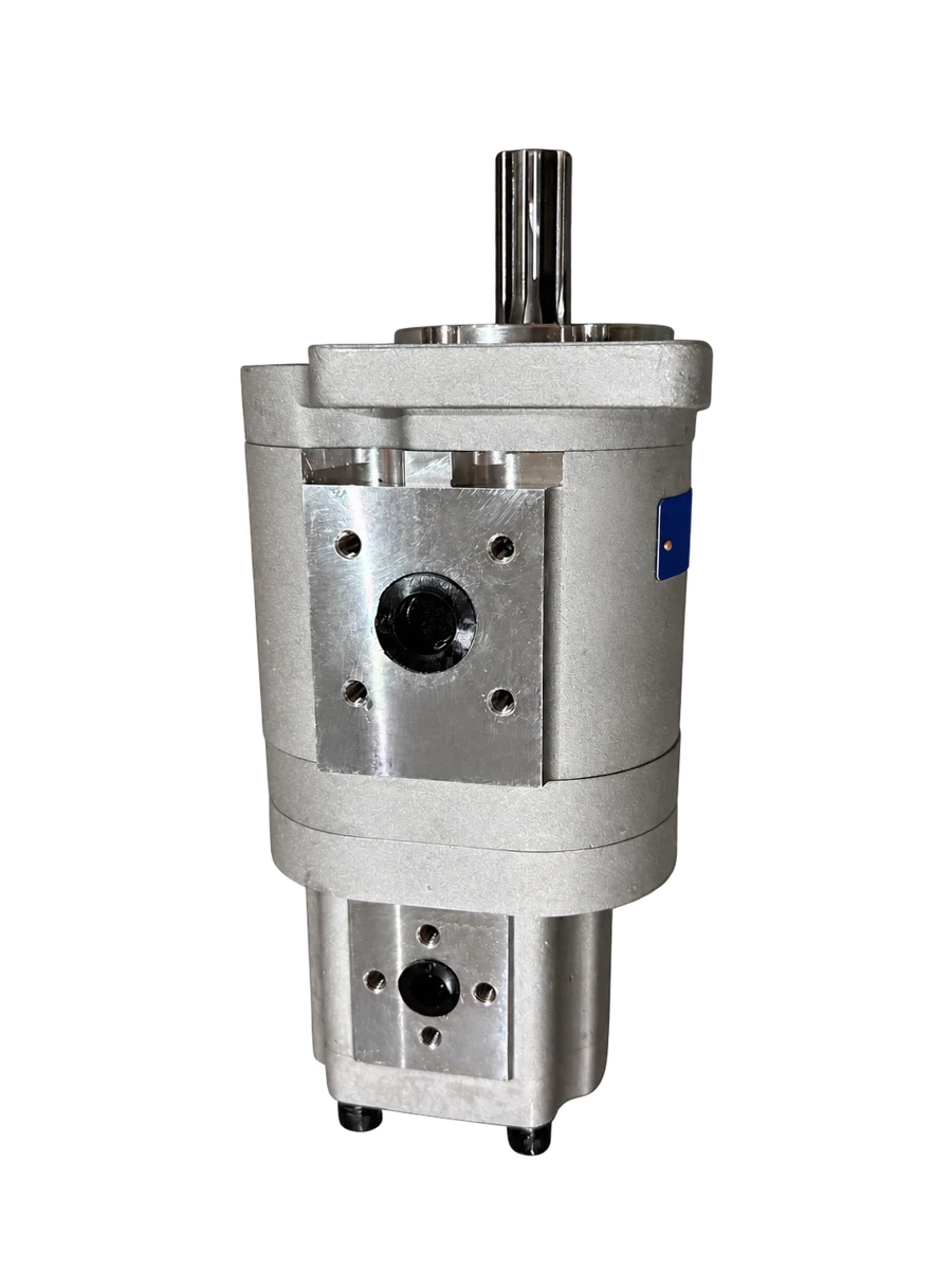
BM2 orbital motor review: specs, torque, displacement, and how it stacks up against BM1, BM3, and OEM equivale…
Mixing used motor oil and hydraulic fluid for recycling? Usually fine, but a few costly exceptions can turn pi…
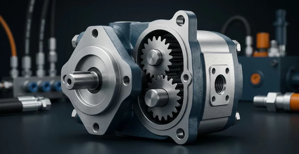
Can you run a hydraulic pump as a motor? The honest answer from a service tech: sometimes yes, often no. Here'…
Contact us now for a professional solution and fast quote.
Fill in your info to start a conversation.