
Diagnosing a failed solenoid takes more than a quick continuity check. A reliable verdict comes from a structured workflow that separates electrical faults from mechanical wear, and isolates the solenoid itself from adjacent circuit components that often mimic its symptoms.
This guide walks through a field-tested diagnostic sequence used by automotive, industrial, and HVAC technicians, with reference values, interpretation criteria, and decision logic for repair-versus-replace calls.
Understanding Solenoid Failure Fundamentals
Before you reach for a multimeter, get clear on what you are actually testing. A solenoid is an electromechanical actuator, and failure can originate in either domain. Misdiagnosis usually traces back to treating it as a purely electrical component.
How a Solenoid Operates Under Load
A solenoid has three functional elements: an electromagnetic coil, a movable iron plunger, and (in switching applications) a set of high-current contacts. Energize the coil and the magnetic field pulls the plunger into the core, mechanically closing the contacts or actuating a valve.
Failure points cluster at predictable locations: insulation breakdown in the coil windings, plunger binding from contamination or wear, and contact erosion from arcing under load.
Common Failure Modes by Type
Diagnostic thresholds vary significantly across applications. A starter solenoid pulling 30+ amps behaves differently than a fuel shutoff drawing under 1 amp, and the resistance values that signal failure differ accordingly.
- Starter solenoids: Contact pitting, plunger sticking, hold-in coil failure
- Fuel solenoids: Coil burnout from overvoltage, plunger gumming from fuel residue
- Hydraulic solenoids: Contamination-induced sticking, coil heat damage
- HVAC/transmission solenoids: Winding shorts from thermal cycling, valve seat wear
Electrical Failures vs. Mechanical Failures
Electrical faults show up as open windings, shorted turns, or insulation-to-case leakage. Mechanical faults present as restricted plunger travel, worn contacts, or broken return springs. That distinction sets your testing path: electrical faults respond to ohmmeter analysis, while mechanical faults require bench actuation testing.
Recognizing Symptoms of a Faulty Solenoid
Field symptoms guide which tests to prioritize. The symptoms of a faulty solenoid are rarely unique to the component itself, so treat each observation as a starting hypothesis rather than a confirmed diagnosis.
Audible and Tactile Warning Signs
A single sharp click usually means the pull-in coil is working but the hold-in circuit or main contacts are failing. Rapid chattering points to insufficient current, often from battery or cable resistance rather than the solenoid itself. Buzzing under load suggests a partial winding short. Abnormal heat at the housing indicates excessive current draw.
Performance-Based Symptoms
No-crank conditions, delayed actuation, partial engagement, and load-dependent dropouts each map to different internal faults. Intermittent failures that worsen with operating temperature almost always indicate heat-sensitive insulation breakdown, which a cold-state test will miss.
Symptom-to-Cause Reference Table
| Symptom | Probable Cause | Confirmation Test |
|---|---|---|
| Single click, no crank | Stuck plunger / low coil current | Voltage drop test |
| Rapid clicking | Insufficient holding current | Battery and resistance check |
| No click, no response | Open coil / no signal | Continuity test |
| Engages then drops out | Shorted windings / heat fault | Hot resistance test |
| Slow actuation | Partial coil short | Inductance/resistance comparison |
Required Tools and Safety Preparation
Reliable diagnostics demand instruments with sufficient resolution. A general-purpose meter that only reads down to one ohm won't cut it on low-resistance starter circuits.
Essential Diagnostic Equipment
- Digital multimeter with 0.1Ω resolution or better
- Clamp ammeter rated for the expected current range
- 12V test lamp for signal verification
- Fused jumper wires (30A inline fuse minimum for starter circuits)
- Insulated probes and back-probe pins for non-destructive measurement
Pre-Test Safety Protocol
Disconnect the negative battery terminal before any disassembly. On solenoids in capacitor-assisted circuits, give the system a minimum 60-second discharge window. Hydraulic and pneumatic solenoids require system depressurization and lockout-tagout per applicable shop standards. PPE means safety glasses and insulated gloves rated for the circuit voltage.
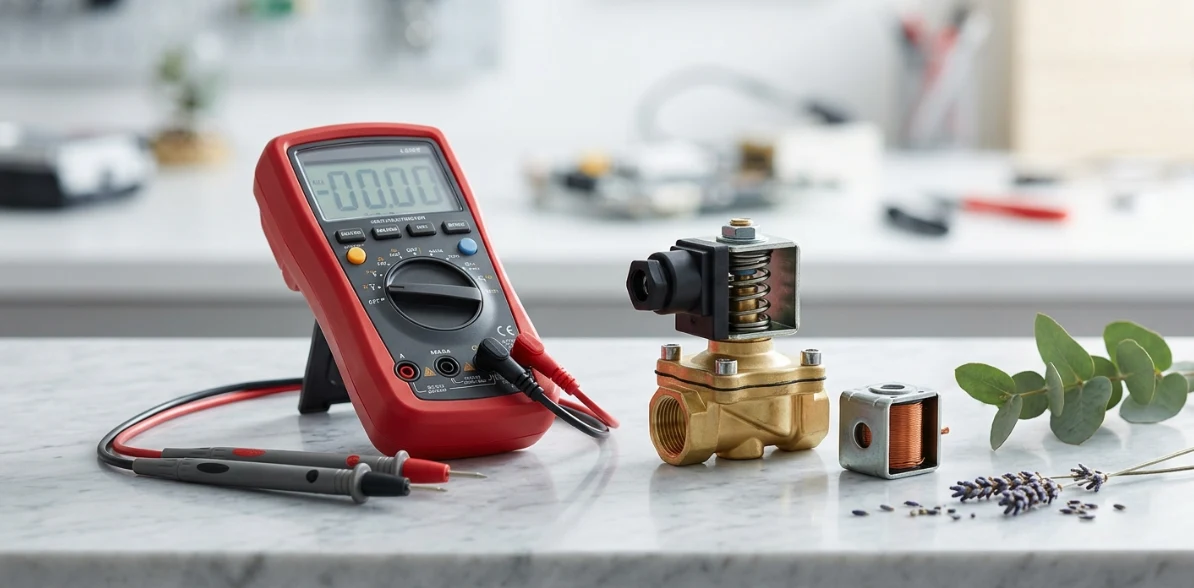
Step-by-Step Solenoid Testing Procedures
Work from non-invasive observation toward load-based testing. Skipping the visual stage is the single biggest source of wasted diagnostic time.
Visual and Physical Inspection
Check terminals for corrosion, oxidation, or loose connections. Inspect the housing for burn marks, cracks, or signs of overheating. Confirm mounting integrity, since a poorly grounded solenoid will throw electrical symptoms with no internal fault. Examine the wiring harness for chafing or melted insulation near the solenoid body.
Continuity Test with a Multimeter
With the solenoid de-energized and isolated, set the multimeter to continuity mode and probe across the coil terminals. A continuous tone confirms an intact winding path. Silence, or an open-circuit reading, confirms coil failure and ends the diagnostic right there.
Probe Placement by Solenoid Type
Terminal mapping varies by configuration. On a 3-terminal starter solenoid, probe between the small "S" terminal and the case ground. For 2-wire fuel solenoids, probe directly across both leads. On 4-terminal hydraulic units, identify the coil terminals from the data plate before testing, since two terminals connect to the coil and two to the position feedback switch.
Resistance (Ohms) Measurement
The solenoid resistance ohms reading is the single most diagnostic measurement you can take. Switch the multimeter to the 200Ω range and probe the coil terminals. Compare results against manufacturer specifications or the reference values below.
Standard Resistance Ranges by Application
| Solenoid Type | Expected Resistance | Indicates Fault If |
|---|---|---|
| Starter solenoid (12V) | 0.4 – 1.0 Ω | <0.2 Ω or >2.0 Ω |
| Fuel shutoff solenoid | 8 – 16 Ω | <5 Ω or open |
| Transmission solenoid | 10 – 30 Ω | Outside ±15% of spec |
| Hydraulic solenoid (12V) | 5 – 9 Ω | <3 Ω or >12 Ω |
| HVAC/door lock solenoid | 40 – 80 Ω | Outside ±20% of spec |
Always subtract test lead resistance (typically 0.1–0.3Ω) from low-range readings. That correction is non-negligible on starter solenoids, where the entire expected range sits under one ohm.
Voltage Drop Test Under Load
A solenoid can pass cold resistance checks and still collapse under load. Energize the circuit and read voltage across the main terminals with current flowing. Anything over 0.2V on starter solenoids, or 0.5V on auxiliary units, points to internal contact degradation, even if the static resistance reads in spec.
Bench Testing with Direct Power
Pull the solenoid, clamp it down, and feed rated voltage through a fused jumper straight to the coil terminals. That isolates it from upstream control-circuit faults, which account for a large share of misdiagnosed cases.
Interpreting Bench Test Results
A clean mechanical click paired with continuity across the load terminals confirms full function. Weak actuation, audible buzzing, no plunger travel, or measured current outside the rated range each confirm failure. Log the measured current draw. It's the clearest read on internal winding condition.
Current Draw Measurement
Clamp a meter around the supply lead during activation. Current well above the rated value points to shorted windings dropping impedance. Current well under spec with no actuation suggests a partial open or a high-resistance internal connection. Compare against the manufacturer's specified inrush and holding current values.
Differentiating Solenoid Faults from Related Issues
The costliest diagnostic mistake is swapping out a working solenoid because something next to it produced solenoid-like symptoms.
Battery and Power Supply Verification
Confirm a minimum 12.4V at rest on a 12V system, with cranking voltage holding above 9.6V under load. A weak battery is the single most common cause of symptoms wrongly pinned on a faulty starter solenoid.
Control Circuit and Relay Checks
Before condemning the solenoid, verify the trigger signal at its control terminal with a test lamp or oscilloscope. A missing or low-voltage trigger signal points to ignition switch faults, control relays, or wiring, not the solenoid.
Ground Path Integrity
Measure resistance from the solenoid case to chassis ground. Anything above 0.1Ω indicates a degraded ground path that mimics internal solenoid failure exactly. Clean and re-torque the ground connection before any replacement decision.
When to Replace vs. Repair
Repair versus replace comes down to construction type and economics. Sealed automotive solenoids are replacement items across the board. Rebuildable industrial units justify repair when downtime cost exceeds parts cost.
Replacement Indicators
- Open coil or shorted windings confirmed by resistance testing
- Pitted contacts past manufacturer service limits
- Cracked housing or compromised insulation
- Sealed assemblies, regardless of fault type
Serviceable Conditions
Surface corrosion on external terminals, loose mounting hardware, contaminated plungers in serviceable units, and dirty contacts in industrial relay-style solenoids can often be brought back without replacement. Record the cleaning method and post-service test values for future reference.
Frequently Asked Questions
What resistance reading indicates a bad solenoid?
Readings significantly outside the manufacturer's specification range, typically below 0.2Ω (shorted) or showing OL/infinite (open), indicate coil failure. Always cross-reference against the application-specific range, since acceptable values run from under 1Ω on starter solenoids to over 40Ω on HVAC units.
Can a solenoid test good but still fail under load?
Yes. Cold resistance can read fine while heat-induced shorts only show up at operating temperature. A voltage drop test under load is the definitive check, backed up by a current draw measurement when intermittent symptoms persist.
How long should a solenoid last?
Service life tracks duty cycle. Quality automotive starter solenoids are rated for 100,000+ cycles. Industrial units built for continuous duty typically come in between 1 and 5 million cycles. Operating environment, switching frequency, and load current all cut that figure down substantially.
Is clicking always a sign of a bad solenoid?
No. Clicking usually means the solenoid is engaging but doesn't have enough current to hold, which points to battery condition, cable resistance, or a bad ground path rather than the solenoid itself. Always verify supply voltage under load before condemning the part.
Can I test a solenoid without removing it?
Most electrical tests, including continuity, resistance, and voltage drop measurements, can be done in-circuit. Mechanical verification on the bench requires removal, so rated voltage can be applied directly to the coil while you watch plunger travel and contact closure.
What's the difference between a relay and a solenoid in testing?
Both use coils and contacts, and the basic continuity and resistance procedures are identical. Solenoids handle higher current and produce useful mechanical motion beyond simple contact closure, so testing also has to verify plunger travel distance and force, not just electrical switching.