How To Add A Hydraulic Pump To A Tractor
Learn how to add an auxiliary hydraulic pump to your tractor. Covers pump selection, installation steps, and t…

| Item | Catalogue and selection information |
|---|---|
| Current assembly reference | T1150-36440 / T115036440 |
| Earlier catalogue references | T1150-36400 / T115036400, T1150-36403 / T115036403, T1150-36407 / T115036407, T1150-36409 / T115036409 |
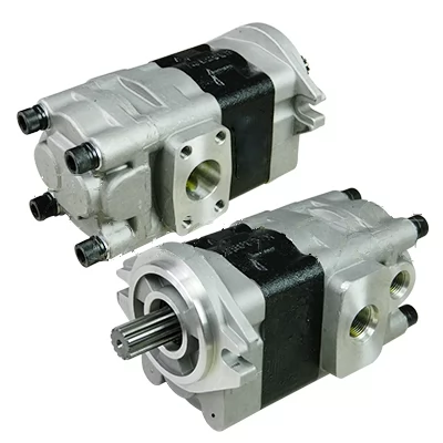
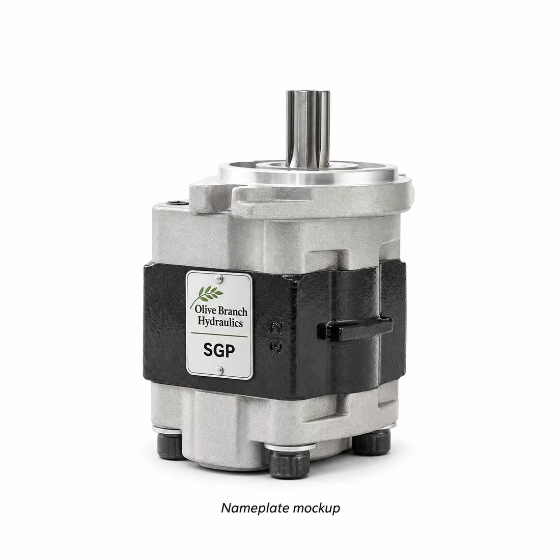
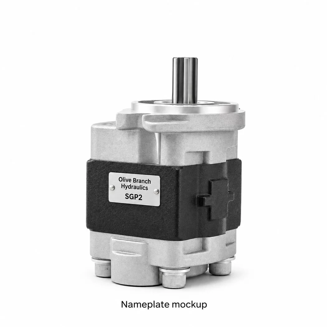
| Photo reference | T1150-36400 configuration, shown from three angles. |
| Equipment examples | Selected Kubota L2501, L2800, L3130, L3240 and L3902DT tractors. Confirm model suffix and serial number. |
| Drive and mounting | External spline in the reference photos. Confirm tooth count, spline diameter, engagement, mounting pilot and bolt centres. |
| Ports and operating data | Verify port sizes, orientation, drive-end rotation, displacement, pressure and speed against the original assembly or approved drawing. |
Kubota L Series Hydraulics
T1150-36440 is the current Kubota assembly reference for the hydraulic gear pump on selected L2501, L2800, L3130, L3240 and L3902DT tractors, and we build it to the configuration confirmed from your original sample or approved drawing.
Four earlier numbers trace to this assembly: T1150-36400, T1150-36403, T1150-36407 and T1150-36409. Coverage applies only to selected tractors within each model, so the model suffix and serial number decide the match, not the model name alone. Production runs from our gear pump plant in Hebei, China, and all quotations are EXW.
The decisive checks are shaft spline, pilot, flange bolt pattern, ports, rotation and duty. Each is confirmed against physical or drawn evidence before a quotation is issued. Dimensions are never taken from a parts diagram.
Current reference — T1150-36440, with hyphenless form T115036440 accepted on all RFQs.
Matching basis — Original sample or approved drawing. A parts diagram identifies the assembly but does not carry dimensions.
Branding — White-label marking and custom packaging are available for distributor and dealer programmes.
One current assembly number and four earlier numbers describe the same Kubota L Series pump position.
T1150-36440 is the current assembly reference. T1150-36400, T1150-36403, T1150-36407 and T1150-36409 are earlier numbers that still appear on pumps in service, on old stock labels and in dealer records. In ERP systems and marketplace listings these numbers often appear without hyphens: T115036440, T115036400, T115036403, T115036407 and T115036409. We cross-reference every one of them, but the configuration we build follows your sample or drawing.
The three product photos on this page show the T1150-36400 reference configuration. They illustrate body layout and port arrangement only. Your production configuration is fixed only after the matching checkpoints below are confirmed.
| Current assembly | T1150-36440 / T115036440 |
|---|---|
| Earlier | T1150-36400 / T115036400 |
| Earlier | T1150-36403 / T115036403 |
| Earlier | T1150-36407 / T115036407 |
| Earlier | T1150-36409 / T115036409 |
Six interface points decide whether a pump fits the tractor. No dimension is assumed.
L3902DT parts diagram 583500, item 010, identifies the T1150-36440 assembly. The diagram is not dimensional, so every value comes from the sample or the approved drawing.
| Checkpoint | What is confirmed | Basis |
|---|---|---|
| Shaft spline | Tooth count, spline type, engagement length | Original sample or approved drawing |
| Pilot | Pilot diameter and fit to the mounting face | Original sample or approved drawing |
| Flange bolt pattern | Hole count, spacing and hole size | Original sample or approved drawing |
| Ports | Thread type, size and orientation of inlet and outlet | Original sample or approved drawing |
| Rotation | Direction viewed from the shaft end | Original sample or approved drawing |
| Duty | Operating conditions stated on the drawing or by the tractor maker | Approved drawing or original sample data |
The assembly covers selected tractors within each model listed, not every unit built.
Selected L2501 tractors use this pump position. Confirm the model suffix and serial number against the pump fitted before ordering.
Coverage depends on the build range, so a serial number outside the confirmed range needs a sample check.
Selected L3240 tractors are covered. Send the suffix, the serial number and the part number from the pump label.
Parts diagram 583500, item 010, lists the T1150-36440 assembly and can serve as the assembly reference. Interface dimensions still come from a sample or an approved drawing.
One confirmed configuration can serve several L models in a region. Stock depth can then follow the actual tractor population rather than separate part numbers.
Torque and pressure values come from the Kubota workshop manual, not from this checklist.
Offer the shaft into the drive and confirm full, free engagement without forcing.
Seat the pilot fully, then confirm all flange holes align without side load.
Compare port orientation and rotation direction with the pump coming off the tractor.
Flush the lines, cap the open ports until connection, and fit new seals of the specified type.
Run at low idle and watch for abnormal noise, cavitation sound or leaks at the flange and ports. Stop and recheck if any appear.
Customers rarely arrive with the current number, so the earlier reference has to be mapped before it is quoted.
A customer holding T1150-36400, T1150-36403, T1150-36407 or T1150-36409 is usually describing the same pump position as T1150-36440. The number alone does not prove an identical interface. When the label is readable and the suffix and serial number fall in the confirmed range, mapping to the current assembly is straightforward. When the label is worn, the serial number is missing or the photos hide the shaft end, the risk is a pump that bolts up but fails on spline, port thread or rotation.
Ask for the physical sample whenever two or more checkpoints cannot be read from photos or a drawing. This adds freight time to the quotation stage. It removes the most common cause of returns.
Distributors gain the broadest coverage by stocking one confirmed configuration under the current number and cross-listing the four earlier numbers. Engineers should sign off only once all six checkpoints are documented. Before dispatch, every pump is checked item by item against that confirmed configuration.
The label shows a legible part number and the serial number is in the confirmed range
An approved drawing covers all six checkpoints
The label is missing or unreadable
The tractor has been modified or rebuilt
These are the local search terms for this pump. Each one pairs with T1150-36440.
Spanish — bomba hidráulica Kubota T1150-36440
French — pompe hydraulique Kubota T1150-36440
Russian — гидронасос Кубота T1150-36440
Arabic — مضخة هيدروليكية كوبوتا T1150-36440
Portuguese — bomba hidráulica para trator Kubota T1150-36440
Turkish — Kubota hidrolik dişli pompa T1150-36440
Our OEM/ODM work runs in four stages, and branding is added once the configuration is fixed.
Send the original pump or an approved drawing, with the tractor suffix and serial number. Drawings can arrive as PDF or native CAD files.
We record the six checkpoints and return a configuration summary for your sign-off. Nothing goes into production before that sign-off.
A sample pump is built to the confirmed configuration for your fitment check. Batch production starts only after you approve the sample.
Each pump is inspected against the confirmed configuration before packing, an approach refined over many years of gear pump manufacturing.
Your brand marking, labels and cartons follow your artwork. MOQ and lead time are quoted per project, because they depend on configuration and packaging scope.
Send the details below and we return an EXW quotation based on the confirmed configuration.
Model, suffix and serial number for each tractor you intend to cover.
Part number from the original pump, clear photos of the shaft end, flange and ports, or an approved drawing.
First-order quantity or annual volume, plus any white-label or packaging requirements.
You receive an EXW Hebei price with MOQ and lead time for the confirmed configuration.
The Kubota L3902DT hydraulic pump component diagram, group 583500, identifies T1150-36440 as the complete pump assembly at item 010. Use the diagram to identify components. Confirm installation dimensions against the original pump or an approved drawing.
Regional search terms: bomba hidráulica de engranajes Kubota T1150-36440 (ES), pompe hydraulique à engrenages Kubota T1150-36440 (FR), шестерённый гидронасос Kubota T1150-36440 (RU), مضخة تروس هيدروليكية كوبوتا T1150-36440 (AR), bomba hidráulica de engrenagens Kubota T1150-36440 (PT), Kubota T1150-36440 hidrolik dişli pompa (TR).
Learn how to add an auxiliary hydraulic pump to your tractor. Covers pump selection, installation steps, and t…
BM2 orbital motor review: specs, torque, displacement, and how it stacks up against BM1, BM3, and OEM equivale…
Skip priming and your gear pump dies in seconds. Learn the 5-minute procedure that prevents scoring, cavitatio…
Learn how to diagnose & repair hydraulic gear pumps fast. Step-by-step guide covers symptoms, root causes & re…
Contact us now for a professional solution and fast quote.
Fill in your info to start a conversation.