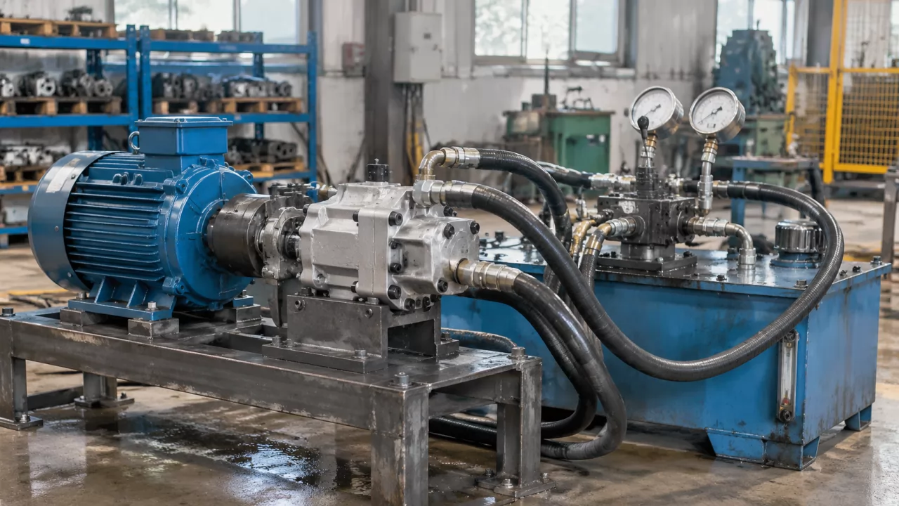
Gear Pump Testing: Pressure, Flow and Leak Checks Before Shipment
Gear pump testing under load shows whether a pump delivers rated flow, holds rated pressure and stays leak-fre…

| Base model | Displacement (mL/rev) | Catalogue regulated flow choices (L/min) | L1 (mm) | L2 (mm) | L (mm) | Weight (kg) |
|---|---|---|---|---|---|---|
| CBTB/QC-F310 | 10 | 12–16 | 48.5 | 91.5 | 111 | 3.5 |
| CBTB/QC-F312 | 12 | 16–18 | 50.5 | 95 | 114.5 | 3.6 |
| CBTB/QC-F314 | 14 | 18–22 | 51.5 | 97.5 | 117 | 3.7 |
| CBTB/QC-F316 | 16 | 19–23 | 53 | 100.5 | 120 | 3.8 |
| CBTB/QC-F318 | 18 | 20–25 | 54.5 | 103.5 | 123 | 3.9 |
Rated pressure: 20 MPa. Maximum pressure: 25 MPa. Optimum speed: 1500–2500 rpm. Catalogue speed range: 800–3000 rpm. Volumetric efficiency: ≥92%. Integrated constant-flow valve in the rear cover.
Mounting: A oval pilot 82.55 mm or A1 oval pilot 80 mm, subject to confirmed configuration. Drawing shows 106 mm mounting-slot centres. Ports: G3/4 inlet, depth 18 mm; G1/2 outlet, depth 16 mm. Shaft options documented: H4 four-tooth rectangular spline and SAE 9-, 10- or 11-tooth spline. Confirm the exact shaft, rotation and complete suffix before ordering.
Olive Branch Hydraulics manufactures hydraulic gear pumps and supports OEM/ODM production, sample-based development and manufacture to approved drawings. The CBTB/QC-F3 configuration combines a gear pumping section with a constant-flow valve assembly in its rear cover. It is intended for hydraulic steering systems on agricultural and mobile machinery, subject to verification of the original installation and duty requirements.
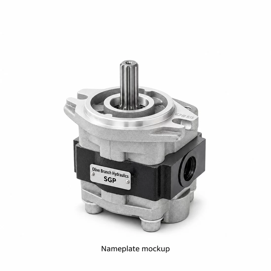
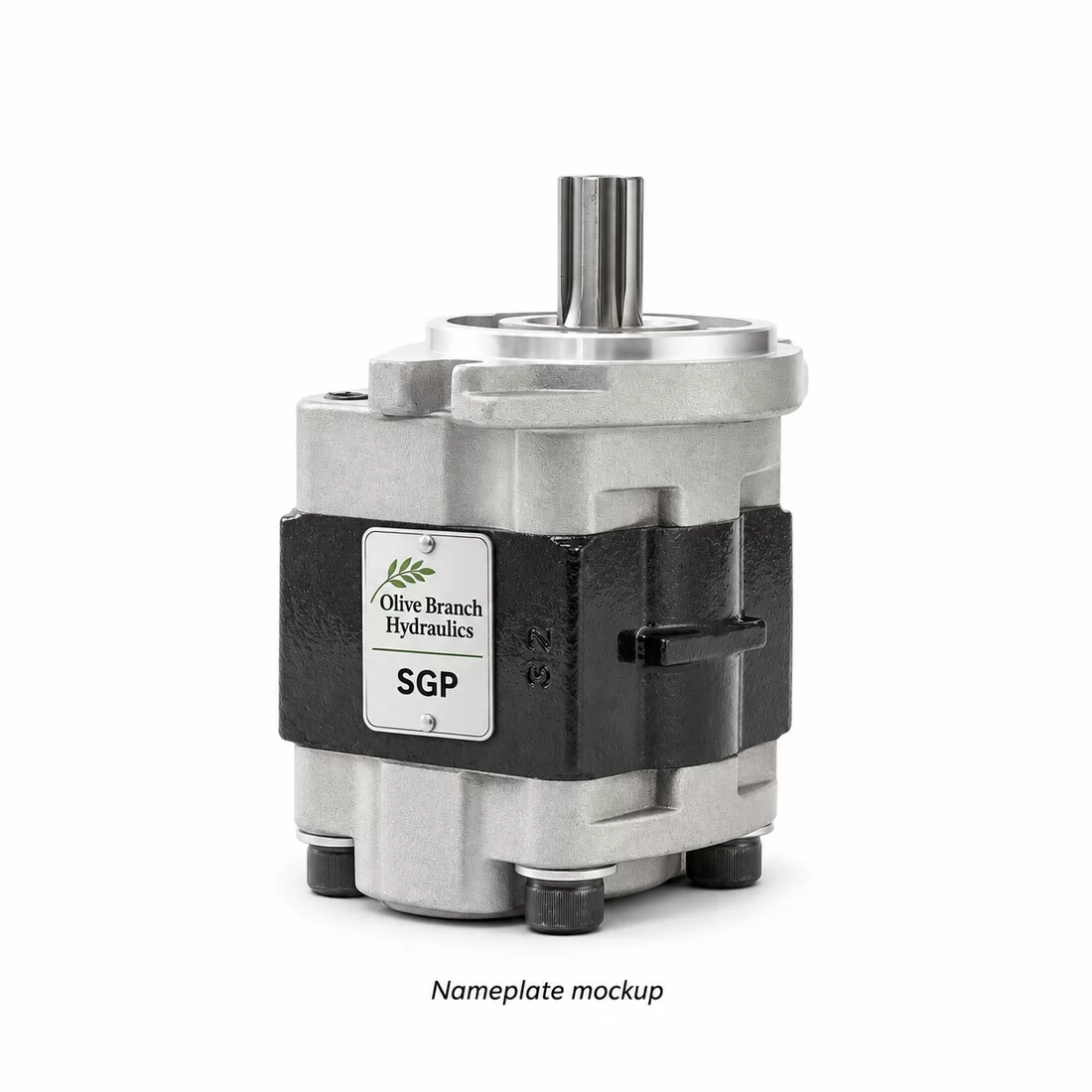
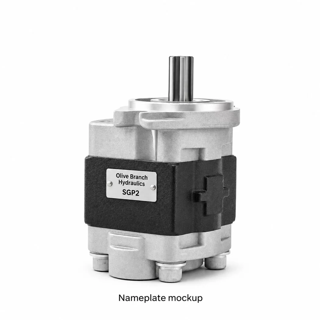
This product groups the five verified base models and documented shaft options for the selected oval mounting style. Two real photographs show the complete pump and its shaft-end arrangement. The original installation drawing is included in the gallery. The photographs illustrate a spline-shaft configuration; they are not separate photographs of every displacement, shaft or rotation choice.
| Base model | Displacement (mL/rev) | Catalogue regulated flow choices (L/min) | L1 (mm) | L2 (mm) | L (mm) | Weight (kg) |
|---|---|---|---|---|---|---|
| CBTB/QC-F310 | 10 | 12–16 | 48.5 | 91.5 | 111 | 3.5 |
| CBTB/QC-F312 | 12 | 16–18 | 50.5 | 95 | 114.5 | 3.6 |
| CBTB/QC-F314 | 14 | 18–22 | 51.5 | 97.5 | 117 | 3.7 |
| CBTB/QC-F316 | 16 | 19–23 | 53 | 100.5 | 120 | 3.8 |
| CBTB/QC-F318 | 18 | 20–25 | 54.5 | 103.5 | 123 | 3.9 |
Displacement is a gear-pump volume per revolution. The regulated-flow figures are catalogue selection ranges, not displacement values and not a promise of that flow at every shaft speed. Regulation requires sufficient pump delivery for the selected flow setting. Confirm the required steering flow, operating speed and valve calibration before manufacture.
Catalogue dimensions and weights refer to the illustrated configuration. Shaft, pilot, rotation and port changes require a confirmed assembly drawing.
Search spellings include CBTB/QC-F3, CBTB-QC-F3, CBTB QC F3, CBTB/QC constant flow pump and CBTB/QC steering gear pump. Individual base models are CBTB/QC-F310, CBTB/QC-F312, CBTB/QC-F314, CBTB/QC-F316 and CBTB/QC-F318. A slash or hyphen spelling variation does not establish a different physical pump.
The catalogue uses patterns such as CBTB/QC-F310-****. Asterisks represent configuration choices and are not a complete orderable part number. F denotes the listed 20 MPa pressure grade; 3 identifies the series. A and A1 identify alternative oval pilots; L identifies screw ports. H4 identifies the four-tooth rectangular spline, while SAE shaft choices require the specific tooth count. Rotation L is counterclockwise and R is clockwise, normally omitted in the catalogue code. Confirm direction as viewed from the shaft end.
No separate machine OEM material number or exact tractor, harvester or loader fitment has been verified for this catalogue configuration. Similar model names from different manufacturers must be checked against the original pump and drawing.
All five listed models have catalogue rated pressure of 20 MPa, maximum pressure of 25 MPa, optimum speed of 1500–2500 rpm and operating range of 800–3000 rpm. Listed volumetric efficiency is at least 92%. Maximum pressure is a catalogue limit, not a continuous-duty operating recommendation. Check oil temperature, inlet conditions, required steering flow and the complete duty cycle when selecting the assembly.
The original drawing lists nominal pilot alternatives of 82.55 mm and 80 mm. The oval mounting outline is 130 mm across, with 106 mm slot-centre spacing and two 11 mm slots shown. Select the pilot and mounting arrangement using the actual machine interface.
The inlet is G3/4, 18 mm deep, with a 45 mm spotface. The outlet is G1/2, 16 mm deep. The drawing includes port seat details; confirm sealing faces, fittings and clearances on the approved installation drawing rather than selecting a fitting from thread size alone.
| Shaft option | Reference drawing information |
|---|---|
| H4 rectangular spline | Four-tooth form; nominal major diameter 18 mm, minor reference 14.4 mm, tooth width 5 mm; 36 mm overall projection reference |
| SAE 9-tooth spline | 16/32 diametral pitch, 30° pressure angle, major reference 15.45 mm, minor reference 12.28 mm; 31 mm projection reference |
| SAE 10-tooth spline | 16/32 diametral pitch, 30° pressure angle, major reference 17.04 mm, minor reference 13.86 mm; 36 mm projection reference |
| SAE 11-tooth spline | 16/32 diametral pitch, 30° pressure angle, major reference 18.63 mm, minor reference 15.46 mm; 31 mm projection reference |
Drawing tolerances control coupling fit. The selected shaft must match the original coupling and engagement length. The original diagram documents these choices; it does not establish that every photograph shows each shaft type.
The catalogue describes a high-strength aluminium-alloy housing, axial clearance compensation, radial balancing and self-lubricating bearings. The rear-cover valve regulates the selected steering flow when delivery is sufficient. Exact equipment fitment requires the original marking, displacement, flow setting, pressure requirements, mounting dimensions, shaft, ports and rotation.
Provide the complete nameplate, clear photographs, original displacement, required regulated steering flow, operating pressure and speed, shaft measurements, pilot and mounting dimensions, port details and rotation. Olive Branch Hydraulics can evaluate your sample or drawing and confirm the assembly and valve calibration for manufacture. An exact new configuration may require a sample and tooling.
Customer search keywords: CBTB QC F3 constant flow steering pump, CBTB/QC-F310 F312 F314 F316 F318 hydraulic pump, agricultural steering gear pump, oval flange constant flow pump, four tooth rectangular spline pump, 9 10 11 tooth SAE spline pump, China hydraulic gear pump manufacturer.
These multilingual product descriptions help customers identify the listed pump family. They are suggested search phrases, not measured keyword-volume data or confirmation of machine compatibility. Use the exact displacement, shaft, rotation and model suffix stated above when making an enquiry.
| Market / language | Product search phrases |
|---|---|
| English — international buyers | CBTB/QC-F3 hydraulic gear pump; CBTB/QC-F3 gear oil pump |
| Russia / Kazakhstan — Russian | CBTB/QC-F3 шестеренный насос; CBTB/QC-F3 гидравлический насос |
| Mexico / Nicaragua / Latin America — Spanish | bomba hidráulica de engranajes CBTB/QC-F3; bomba CBTB/QC-F3 |
| Egypt / Iraq / Arabic-speaking markets | مضخة تروس هيدروليكية CBTB/QC-F3 |
| Türkiye — Turkish | CBTB/QC-F3 hidrolik dişli pompa; CBTB/QC-F3 dişli pompa |
| Brazil — Portuguese | bomba hidráulica de engrenagens CBTB/QC-F3 |
| Vietnam — Vietnamese | bơm bánh răng thủy lực CBTB/QC-F3 |
| Indonesia — Indonesian | pompa roda gigi hidrolik CBTB/QC-F3 |
| French-speaking markets | pompe hydraulique à engrenages CBTB/QC-F3 |
Search family reference: CBTB/QC-F3. The complete verified model patterns, observed markings and configuration details are retained in the technical table and product description above. Family names, model codes and displacement codes are not independently verified equipment OEM material numbers. No additional machine OEM material number or cross-reference has been established for this specific assembly from the verified information available for this listing. Supply the original pump nameplate or equipment parts catalogue to verify an equipment number before ordering.
Do not assume interchangeability from a shared model prefix. Shaft, flange, ports, rotation, pressure grade and dimensions must correspond to the selected approved specification.
Gear pump testing under load shows whether a pump delivers rated flow, holds rated pressure and stays leak-fre…
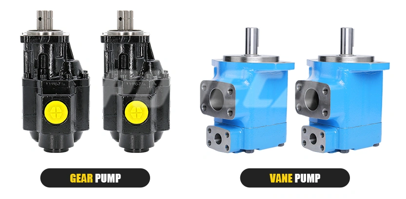
Vane pump vs gear pump: Compare efficiency, noise, cost & applications to find the best hydraulic pump for you…
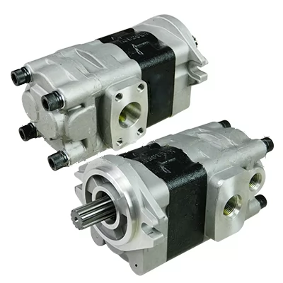
Discover if gear pumps can safely run in reverse. Learn about bidirectional operation, seal design, and key tr…
Learn how to diagnose & repair hydraulic gear pumps fast. Step-by-step guide covers symptoms, root causes & re…
Contact us now for a professional solution and fast quote.
Fill in your info to start a conversation.