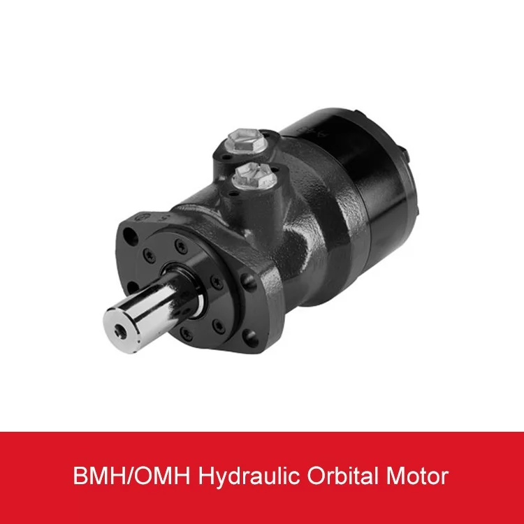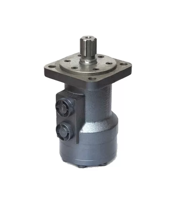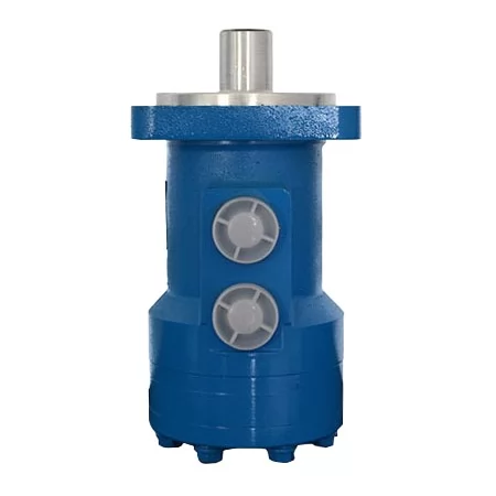

On the workbench, a new orbital hydraulic motor is still disconnected. The ring around its output shaft looks higher on one side. Keep the motor uninstalled, with its port caps fitted, until the supplier identifies the visible part and confirms its seating for the full model code. A short photo set and the matching parts drawing give the supplier a basis for that decision.
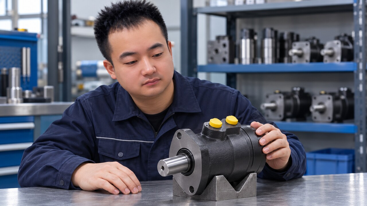
Figure 1. A pre-installation bench inspection of an orbital motor. AI-assisted workshop illustration.
Is the Ring at the Shaft End a Dust Wiper or the Orbital Motor Shaft Seal?
The visible ring at an orbital motor's output shaft is not always the seal that holds oil in. To identify it you need three things: the full nameplate code, the production revision if one is shown, and the supplier's section or parts drawing for that configuration. Shaft-end assemblies differ between series and builds.
Dust wiper, shaft oil seal or another shaft-end part
A dust wiper is an outer lip ring that keeps dirt, water and grit away from the shaft opening, on designs that include one. A shaft oil seal is the sealing element that keeps hydraulic fluid inside the housing. Its lip profile, material and position belong to a design-specific assembly, so it cannot be judged in isolation.
The ring you can see might be either part. It might also be something else, such as a retaining ring, spacer or protective component, depending on the design. Appearance alone cannot tell you whether a part has shifted or was built that way. Lighting, assembly grease and the angle of view can all make a correctly seated ring look off-center.
Why a section or parts drawing settles the question
Seal stacks and seating depth vary by series, configuration and production revision. A motor from another batch, or a similar code on the shelf, is therefore a poor reference. Two units can look alike from the outside and still use different shaft-end parts.
Ask the supplier for a section or parts drawing that matches your full model code. Ask for written confirmation of two things: which component is visible, and how it should sit. This gives you a clear decision point. Until the supplier confirms both points in writing, the motor stays off the machine.
Note: Do not push, pry, tap or open the unit while you wait. Pressing a ring "back into place" can damage a seal lip or wiper that was correctly seated. Opening the housing changes the as-received condition the supplier needs to review.
What Should You Photograph Before Asking the Supplier?
Take three clear photos at the bench with the port caps still fitted. Capture the nameplate, a straight-on shaft-end view and an angled close-up. Add a fourth photo if you see packaging damage, a dent or an apparent fluid trail. Sharp focus and even light matter more than camera quality.
Bench steps for an orbital hydraulic motor inspection
Work through the bench steps in order. Each step can be checked off before you move on, and none of them disturbs the shaft end.
- Leave the shipping plugs and port caps in place so no contamination enters the ports.
- Keep the carton, inner wrapping and any foam or blocking exactly as they arrived.
- Read the nameplate in full and write down every character of the model code and any revision marking.
- Support the motor securely on a clean, stable surface. Position the light so the full ring is visible.
- Photograph the shaft end without cleaning it, rotating the shaft or pressing the ring.
- Store the photos with the order reference and the date you received the motor.
If the shaft end has visible grease or packing residue, leave it alone. Cleaning it can move a loose part or remove a trace that matters to the review.
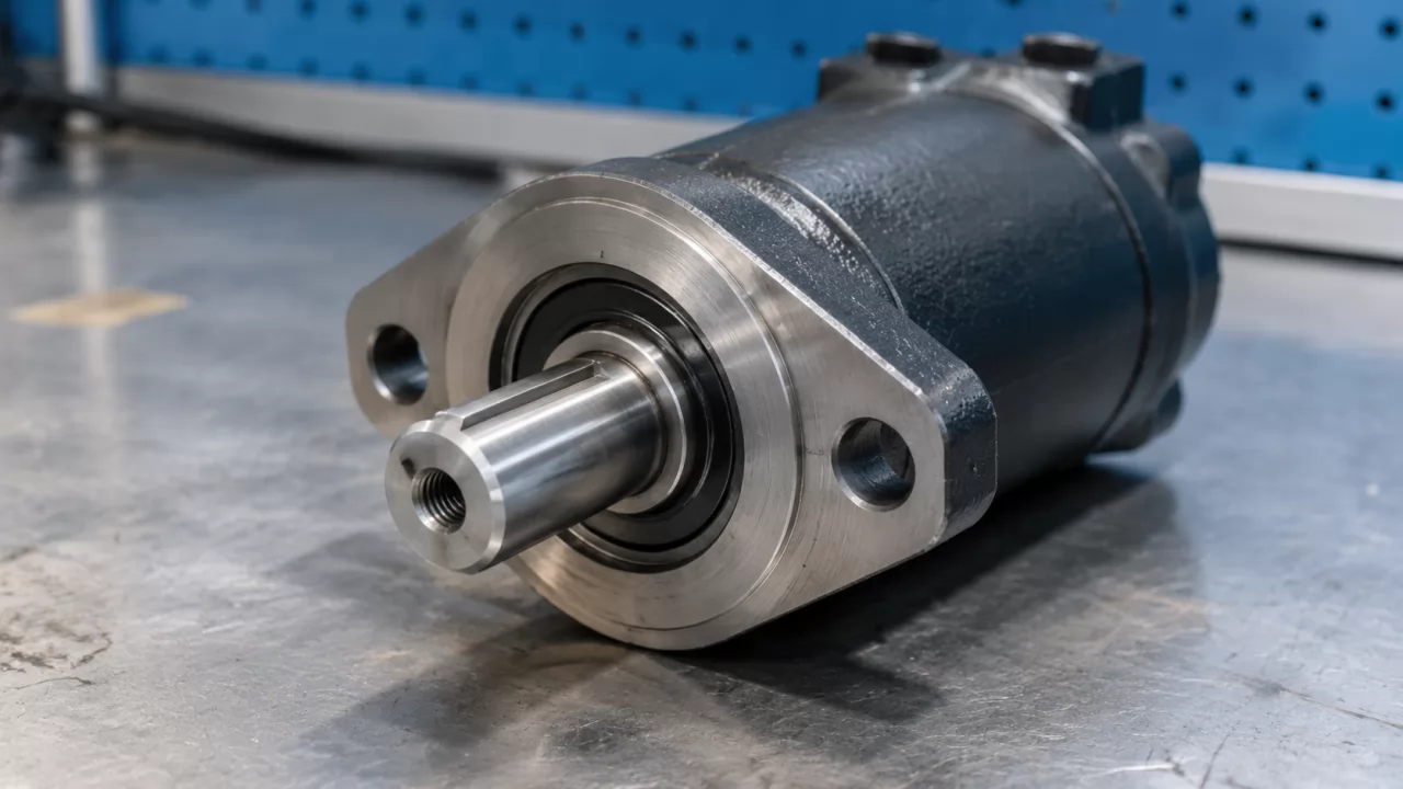
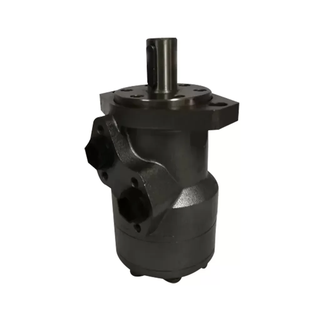
Figure 2. An angled view of the output shaft and surrounding ring. AI-generated illustration of the photo angle.
Photo angle and evidence to capture
The table lists what each shot should show and why the supplier needs it. Use it as a shot list. The centered and oblique views together carry most of the evidence.
| Photo angle | Evidence to capture | Why it helps |
|---|---|---|
| Nameplate, straight on | Full model code and revision marking | Links the part to the right drawing |
| Shaft end, centered | Ring position relative to shaft and bore | Shows the full circumference and any apparent offset |
| Oblique close-up of ring | Ring edge, lip and seating face | Shows the visible edge and any apparent gap |
| Packaging or marks, if present | Carton damage, dents, oil marks | Records transit impact or apparent seepage |
Perspective and lighting can exaggerate or hide an apparent offset. Send both angles and ask the supplier to confirm the acceptance criteria for your exact build.
How Do You Confirm Hydraulic Motor Replacement Fitment?
Hydraulic motor replacement fitment is set by the exact model code and the approved drawing. Appearance and brand cross-references do not settle it. Match the full mechanical interface and the operating data for your machine. Treat physical fit and operating requirements as two separate checks, because a motor can bolt on correctly and still be unsuitable for the duty.
Interface data to send with the photos
Send the interface data together with the photos. Then the supplier can check the shaft-end question and the replacement match in one review.
- Record the full model code and the displacement.
- Confirm the shaft type and its diameter or spline details, plus the shaft extension.
- Measure or copy the pilot diameter and the bolt centers or PCD from the drawing.
- Note the port thread, port seal type and port orientation.
- Describe the case-drain routing and required rotation, with the viewing end specified.
- State the duty cycle, flow, pressure drop, output speed and load the motor must handle.
Use the interface measurements to check whether the motor will mount, couple and connect. Use the circuit and duty data to check whether it can operate as required. Specify which end you viewed when recording clockwise or counterclockwise rotation.
Using series pages to compare configurations
Series pages are useful for narrowing options. The BMR orbital hydraulic motor and BM2 series hydraulic motors pages show which configurations exist within each line. You can compare shaft, flange and port options before you request an approved drawing for a specific code. These pages are not interchangeability charts. Two codes from the same series can still differ at the shaft end, so confirm those parts against the drawing.
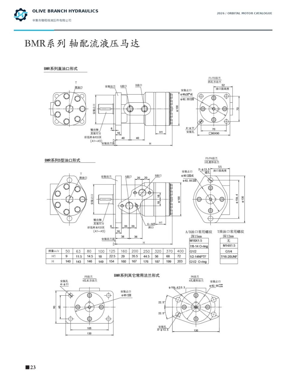
Figure 3. BMR mounting flange and port options from the Olive Branch Hydraulics catalogue, p. 23. Confirm the dimensions on the approved drawing for your exact code.
Mounting checks a manufacturer manual includes
White Drive's OMR Orbital Motors ATEX User Manual (pp. 4, 14–16) is one manufacturer's example of installation guidance. Before mounting, it covers:
- securing the machine and relieving pressure
- checking mounting flange contact and shaft alignment
- keeping shipping plugs in place until connections are made
- reviewing the drain for the selected configuration
Read it as an illustration of the kind of checks a manual sets out. Its ratings and procedures apply to that motor family only. Your motor's own documentation governs your installation.
Why Check the Orbital Motor Case Drain Before Fitting?
When the motor requires a separate case-drain line, that line returns internal leakage from the housing to the tank. The drain routing affects the pressure the shaft seal sees. Confirm how the drain port is used in the approved circuit before installing the replacement.
Danfoss's Orbital Motors General technical information (pp. 19–20) illustrates how the seal, internal check valves and drain configuration affect shaft-seal pressure. Return-line pressure and case-drain pressure are measured at different locations. Use the exact motor's documentation to check the applicable limit at the intended speed and operating condition.
If Oil Appears Near the Shaft After Startup
Stop the machine. Have a qualified technician secure it, isolate the energy sources and relieve stored hydraulic pressure according to the machine instructions before inspecting the motor. Once it is safe to inspect, trace the fluid to its source. Oil from a fitting or housing joint can reach the shaft area.
Safety: Keep hands away from suspected pressurized leaks. Escaping hydraulic fluid can penetrate skin.
FAQ
Can I install the motor if the ring looks only slightly off-center?
No, not until the supplier confirms it. A slight visual offset may be normal for that design, or it may not. Only the drawing for your full code and the supplier's written confirmation can tell you which.
Is it safe to press the ring back into place myself?
No. Pressing or prying can damage a seal lip or wiper that was correctly seated. It can also complicate any warranty review. Leave the shaft end untouched and send photos instead.
Does every orbital motor need a separate case drain line?
Not necessarily. Whether a drain line is required depends on the motor configuration, its check-valve arrangement and the operating conditions stated in that motor's documentation. No universal rule covers every orbital motor.
Will a motor with the same displacement fit my machine?
Not automatically. Displacement is one data point among many. Shaft, pilot, bolt pattern, ports, drain routing, rotation and duty must all match the approved drawing for the exact code.
Request a Fitment Review Before You Fit the Motor
Send the full nameplate code, your photos and the interface data through the Olive Branch Hydraulics contact page. If you are checking a replacement, include the approved drawing or the original part number, plus the machine model and operating conditions. Ask us to review the shaft, flange, ports and drain arrangement for the configuration you are considering.