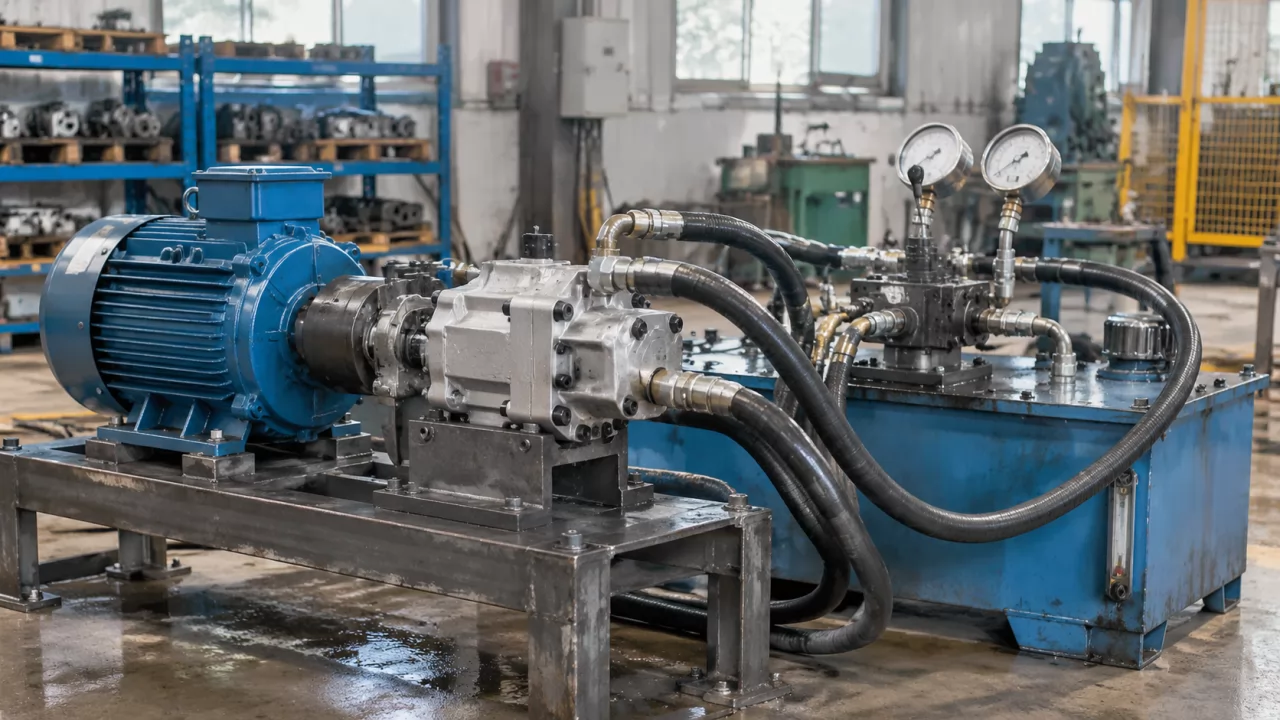
Test des pompes à engrenages : contrôles de pression, de débit et d'étanchéité avant expédition
Le test des pompes à engrenages sous charge permet de vérifier que la pompe fournit le débit nominal, maintien…

| Modèle de la famille du catalogue | Cylindrée (ml/tr) | Débit régulé sélectionnable (L/min) | Pression nominale (MPa) | Pression maximale du catalogue (MPa) | Plage de réglage de la soupape de sûreté (MPa) | Vitesse nominale (tr/min) | Plage de vitesse de fonctionnement (tr/min) |
|---|---|---|---|---|---|---|---|
| HLCB-D00/06 | 6 | 4 / 6 / 8 | 10 | 12.5 | 5–12.5 | 2000 | 800–3000 |
| HLCB-D00/10 | 10 | 8 / 10 / 12 | 10 | 12.5 | 5–12.5 | 2000 | 800–3000 |
| HLCB-D00/16 | 16 | 12 / 14 / 16 | 10 | 12.5 | 5–12.5 | 2000 | 800–3000 |
| HLCB-D00/20 | 20 | 16 / 18 / 20 / 25 | 10 | 12.5 | 5–12.5 | 2000 | 800–3000 |
Le champ 00 est un espace réservé du catalogue pour la valeur de débit régulé sélectionnée. Le débit régulé nécessite une capacité de refoulement suffisante pour la pompe et un point de fonctionnement approprié ; il n'est pas garanti en dessous du seuil de régulation ni à toutes les combinaisons de pression et de vitesse.
| Élément de sélection | Spécification |
|---|---|
| Construction | Pompe à engrenages externes avec ensemble intégré de débit constant et de soupape de décharge |
| Montage représenté | Bride frontale rectangulaire à quatre trous ; la finition du couvercle et la disposition du couvercle de soupape varient selon les exemples de référence |
| Options d'arbre | Arbre cylindrique à clavette et détails de référence de cannelure rectangulaire ; confirmer les dimensions complètes et l'accouplement avant la commande |
| Rotation | L : sens antihoraire / gauche ; option sens horaire / droite selon le code complet du catalogue. Confirmer le sens de visualisation. |
| Orifices | La fiche de contour sélectionnée indique M18 × 1.5 dispositions d'orifices arrière/d'extrémité et latéraux. Vérifier le couvercle réel, la fonction entrée/sortie et la tuyauterie. |
| Référence OEM / matériau | Aucune référence universelle d'équipement vérifiée. Établir le devis à partir de la plaque signalétique, du code complet de débit/cylindrée et du plan approuvé. |
| Applications d'équipement | Systèmes de direction hydrauliques pour engins agricoles et autres machines mobiles ; l'adaptation exacte à la machine nécessite une vérification dimensionnelle et du circuit. |
Olive Branch Hydraulics is a Chinese hydraulic component manufacturer supporting OEM/ODM production, custom tooling and sample-based development. The HLCB-D family combines an external gear pump with a constant-flow control and relief-valve assembly. It is intended for hydraulic steering applications where the steering circuit requires a selected regulated flow as drive speed changes.
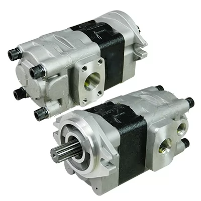
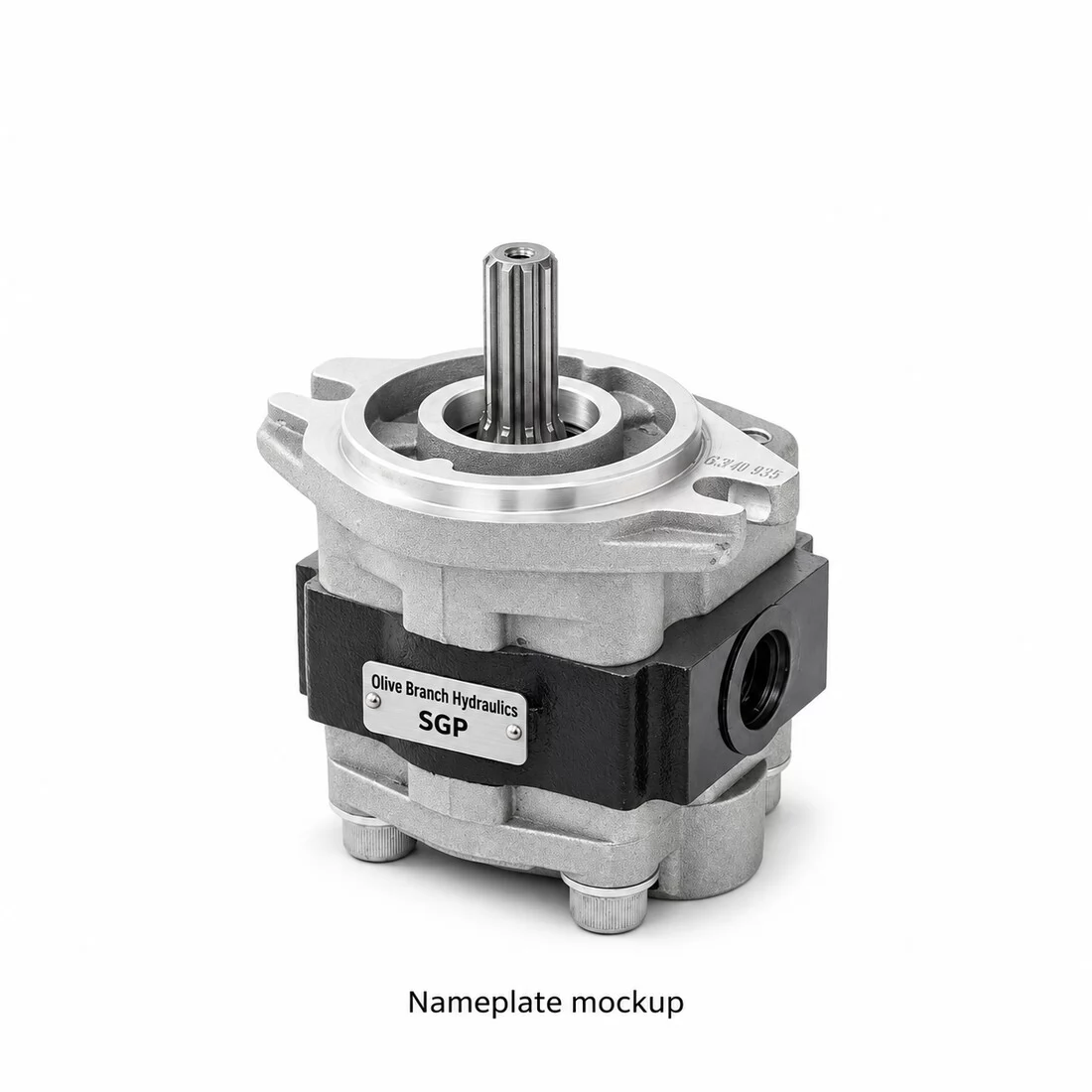
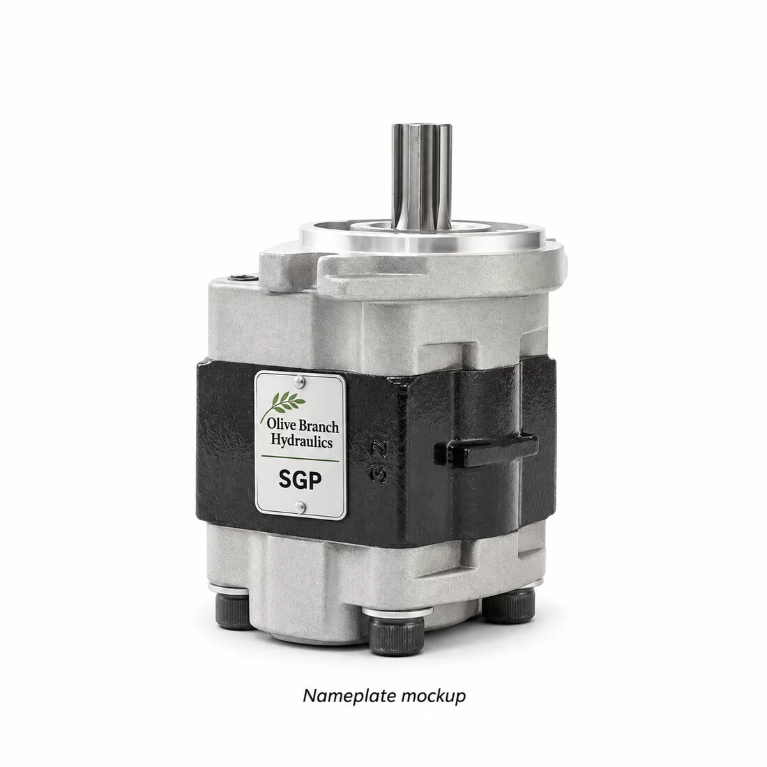
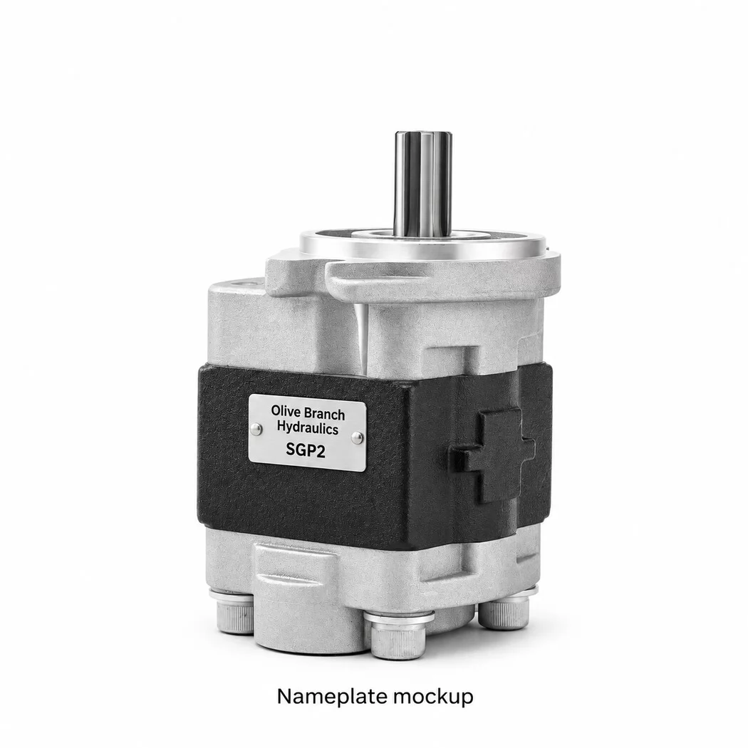
This product groups the selected rectangular four-hole flange configuration, shaft choices and flow/displacement designations on one page. The approved reference photographs include a marked HLCB-D06/06 example, a silver-finish cover example and a comparison of valve-cover arrangements. These are configuration references rather than three angles of one identical assembly. The gallery also includes the original installation and shaft-detail sheet.
The selected catalogue lists 6, 10, 16 and 20 ml per revolution. Its regulated-flow choices produce the thirteen base designations below. The first numeric field identifies the selected constant-flow setting in litres per minute; the field after the slash identifies gear displacement in millilitres per revolution. For example, HLCB-D06/06 identifies a 6 L/min flow choice with a 6 ml/rev gear section. The two numbers are different quantities even when their numeric values match.
| Complete base flow/displacement designation | Regulated flow setting (L/min) | Gear displacement (ml/rev) |
|---|---|---|
| HLCB-D04/06 | 4 | 6 |
| HLCB-D06/06 | 6 | 6 |
| HLCB-D08/06 | 8 | 6 |
| HLCB-D08/10 | 8 | 10 |
| HLCB-D10/10 | 10 | 10 |
| HLCB-D12/10 | 12 | 10 |
| HLCB-D12/16 | 12 | 16 |
| HLCB-D14/16 | 14 | 16 |
| HLCB-D16/16 | 16 | 16 |
| HLCB-D16/20 | 16 | 20 |
| HLCB-D18/20 | 18 | 20 |
| HLCB-D20/20 | 20 | 20 |
| HLCB-D25/20 | 25 | 20 |
These designations follow the selected catalogue options. Confirm the complete suffix, rotation, cover, shaft, port arrangement and valve calibration for the actual order. Other HLCB catalogues may use additional displacement ranges or different code conventions; those configurations require a separate technical review before being treated as the same assembly.
| Base designation | Search formatting variants |
|---|---|
| HLCB-D04/06 | HLCBD04/06 / HLCB D04/06 / HLCB/D04/06 |
| HLCB-D06/06 | HLCBD06/06 / HLCB D06/06 / HLCB/D06/06 |
| HLCB-D08/06 | HLCBD08/06 / HLCB D08/06 / HLCB/D08/06 |
| HLCB-D08/10 | HLCBD08/10 / HLCB D08/10 / HLCB/D08/10 |
| HLCB-D10/10 | HLCBD10/10 / HLCB D10/10 / HLCB/D10/10 |
| HLCB-D12/10 | HLCBD12/10 / HLCB D12/10 / HLCB/D12/10 |
| HLCB-D12/16 | HLCBD12/16 / HLCB D12/16 / HLCB/D12/16 |
| HLCB-D14/16 | HLCBD14/16 / HLCB D14/16 / HLCB/D14/16 |
| HLCB-D16/16 | HLCBD16/16 / HLCB D16/16 / HLCB/D16/16 |
| HLCB-D16/20 | HLCBD16/20 / HLCB D16/20 / HLCB/D16/20 |
| HLCB-D18/20 | HLCBD18/20 / HLCB D18/20 / HLCB/D18/20 |
| HLCB-D20/20 | HLCBD20/20 / HLCB D20/20 / HLCB/D20/20 |
| HLCB-D25/20 | HLCBD25/20 / HLCB D25/20 / HLCB/D25/20 |
HLCB-D00/06, HLCB-D00/10, HLCB-D00/16 and HLCB-D00/20 are family patterns with an unresolved flow field. HLCB/D00/06 is another formatting style used in the referenced catalogue. The 00 placeholder is not a zero-flow production specification. Spacing and punctuation variants help locate enquiries but do not establish compatibility between different manufacturers.
The technical sheet provides a straight-keyed shaft reference and a four-tooth rectangular spline reference. Keep different shaft options within this family while identifying each configuration clearly. Confirm shaft diameter, key or spline dimensions, projection and coupling engagement. The photographs do not establish that every flow/displacement combination is available with every shaft shown.
The installation sheet shows four 9 mm mounting holes on a rectangular pattern, with 70 and 100 mm centre distances, and a 38 mm locating-pilot reference. Its straight-keyed shaft detail uses an 18 mm diameter reference. These figures apply to the illustrated configuration only. Obtain an approved drawing for the chosen cover and shaft before machining or installation.
| Catalogue displacement pattern | Reference L1 (mm) | Reference L (mm) |
|---|---|---|
| HLCB/D00/06 | 45 | 85 |
| HLCB/D00/10 | 48 | 88 |
| HLCB/D00/16 | 53 | 93 |
| HLCB/D00/20 | 56 | 96 |
L1 and L follow the source sheet notation. Valve-cover geometry, port position and total installation envelope must be confirmed separately for the ordered assembly. The comparison photograph shows differing cover arrangements; visible plug locations alone do not identify the hydraulic circuit or valve setting.
The selected catalogue gives 10 MPa rated pressure, 12.5 MPa maximum pressure, a relief adjustment range of 5–12.5 MPa, 2000 rpm rated speed and an 800–3000 rpm working range. A marking on an individual reference unit is not a universal continuous-pressure rating for the family. Specify the required relief calibration and duty cycle when requesting a quotation.
Constant-flow control works within its regulating conditions. At low drive speed, available pump delivery can be insufficient for the selected flow setting. Check the steering demand, minimum engine speed, pressure, fluid temperature, bypass circuit and heat load with the application review. The relief valve must be calibrated to the machine requirement rather than adjusted from a generic catalogue figure.
For agricultural power steering and other mobile hydraulic systems, supply the existing pump nameplate, machine information, shaft measurements, flange dimensions and port layout. A base family code alone does not prove compatibility with a particular tractor or harvester. Any verified equipment material number is recorded against the confirmed drawing; no unverified universal OEM number is assigned.
For manufacturing or an identical-interface request, send a dimensioned drawing or physical sample, the required regulated flow, displacement, relief setting, rotation and quantity. Custom development, sample inspection, production testing, packaging and delivery terms are agreed against the approved technical specification. Search terms: HLCB-D steering gear pump, HLCB constant-flow relief pump, HLCB-D06/06, agricultural power steering pump, tractor steering hydraulic pump, keyed shaft steering pump, rectangular spline gear pump, OEM ODM hydraulic pump manufacturer.
Le test des pompes à engrenages sous charge permet de vérifier que la pompe fournit le débit nominal, maintien…
Découvrez le fonctionnement des vannes de contrôle directionnel hydrauliques. Explorez le fonctionnement du ti…
Pompe à palettes vs pompe à engrenages : Comparez l'efficacité, le bruit, le coût et les applications pour tro…
Découvrez si les pompes à engrenages peuvent fonctionner en toute sécurité en sens inverse. Renseignez-vous su…
Contactez-nous dès maintenant pour une solution professionnelle et un devis rapide.
Fill in your info to start a conversation.